A Dirt Cheap F*** Awesome Interactive Led Table
By Vince on 2016-12-19, 22:12 - Electronics - Permalink

tl;dr
What ?
- led coffee table
- touch-sensitive
What's special about it ?
- IR detection through tranclucent acrylic
- 3 devices connected to a Raspberry Pi via a single serial port
- Java program hacked without modifying the actual code
- 130 EUR (140 USD)
It's finally time I document this project I completed almost one year ago.
I wanted to play with large led displays for a long time (who doesn't ?), and browsing on AliExpress, I once landed on one of those WS2811/WS2812 addressable led strips for less than 3 EUR/meter, and thought "Wow, that's dirt cheap !".
I bought one meter just to play with it, and was surprised to see how fun it was (easy to control and quite powerful), and I started to think about wiring them in a matrix shape. Most of the libraries already support custom width and height, so that's pretty cool.
A few weeks later, I came across that large led matrix by GreatScott and I thought "F*** Awesome !", and following hours of youtube suggestions, I stumbled upon this video by yohash84 and said to myself "interactivity, mmmhhh".
And so the idea was born: I want a Dirt Cheap, F*** Awesome, Interactive Led Table.
First Things First: Non-interactive Version
After a proof of concept with just my 1m long strip, cells delimited with carboard and a thin tracing paper diffuser, I was rather confident that using a strip was a simple and effective solution, and set a non-interactive table as my first goal.
Hardware
I started with IKEA's hacker-friendly Lack table. Its honeycomb cardboard structure makes it really easy to get a hollow table.


So first some calculations: I'll be using a strip with a density of 30 led/m, which leads to 3.33x3.33cm per matrix cell. The LACK table is 55x55cm, but the matrix cannot go from edge to edge because each corner of the table contains a bloc of particle wood (see picture above) to which the foot is attached. The frame is about 1cm and blocks are about 4x4cm each but I figured I could chop the inner corners of the blocks to maximise surface, so I settled on a matrix of 14x14 cells (or 46.67x46.67cm). The ~4 cm left around the matrix will be used to hide connections and will help the table remain sturdy. So here's the "final cut":

OK, with these numbers, the absolute minimum bill of material is:
- Lack table: 6 EUR
- Led strip 7m, 30 led/m (which makes 210. I need 14x14=196): 19 EUR
- Power Supply : 5V 20A (196 x 3 x 20mA = 12A required for the leds alone): 14 EUR
- Controller: Arduino Nano clone: 2 EUR
- Translucent acrylic plate: This is the hardest part to find cheap
 . I ended up buying it locally but I it's available online for 26.5 EUR, including s/h
The rest (remains of white paint, cardboard, wires, etc.) I had laying around.
Less than 70 EUR qualifies for "cheap", and if you can find or recycle a power supply or an acrylic plate, you qualify for "dirt cheap"  .
.
To create cell separations, I used thin corrugated cardboard but quickly found that cutting rectangular noches with regular spacing and depth was a very tedious task, so I piled up all the cardboard strips, stuck them between two old wooden planks and let my circular saw do the job...


Note that I first painted the cardboard, as well as the inside of the table and 4 small pieces of wood for the 4 inner sides in white. That way, inner reflections will increase brightness and level out the intensity of each cell. I should have taken more care though, because the veneer wood layer of the LACK table is so thin that my masking tape pulled it out at places . I guess you get what you pay for.

I then pasted 14-led segments of the the self-adhesive strips to the bottom of the table, and connected the signal in series from line to line (in a zig-zag fashion), while the power for each segment is distributed from a central point to avoid the voltage drop across the 7-meter strip.


The result with the acrylic plate (protection sheet not fully removed yet) is quite satisfactory :
Software
Arduino Nano
The animation above is simply the output of the XYMatrix example which is part of the FastLed library - highly recommended !
Raspberry Pi
For more complex animations, and to handle the interactive part, small microcontrollers would probably be very limiting, so I switched to a Raspberry Pi as the main controller.
Without any doubt, the king of diy led matrix animation software is Glediator. On the plus side, it's a really neat piece of software which allows highly customised animations and supports many matrix types and configurations, and it's free . It is written in Java, which is a surprising decision for a software where performance is important, but it runs relatively well on the Raspberry Pi. However, the main drawback is that it's not open source...
In that configuration, the Arduino Nano is used as a converter from the Pi's serial signal to the WS2812 protocol. That is required because the Glediator running on Linux can suffer inaccurate timings due to the non-realtime OS, the Java VM garbage collection, etc., while the WS2812 leds requires a very precisely timed data stream.
I had a Raspberry Pi 2 laying around so I used that but probably a Raspberry Pi Zero or an Orange Pi could do the job for less. Anyway, let's say 33 EUR for a RPi 3 to be futureproof.
So here are the steps I took to set up the system:
- Install VNC on Pi (see here).
- Free the serial port of the Pi (used for debug and as a shell by default in the distribution) using raspi-config in recent distributions - see here.
- Install RxTx Java serial lib on Pi using "sudo apt-get install librxtx-java"
- Unzip Glediator on the Pi and create a startup script in the "dist" folder as follows:
#!/bin/sh
CLASSPATH=/usr/share/java/RxTxcomm.jar
LDLIBRARYPATH=/usr/lib/jni
java -Djava.library.path=/usr/lib/jni -Dgnu.io.rxtx.SerialPorts=/dev/ttyAMA0 -jar Glediator_V2.jar
- For the Arduino Nano, use the Arduino sketch provided on Glediator's website.
- Start Glediator and configure matrix size (14x14) and pattern (in my case VS_BL for Vertical Snake starting at Bottom Left) "Output" in Glediator protocol in GRB with the serial port on 115200 bauds.
A note about baudrate: Most websites talk about a baud rate of 1000000 or 500000 bps, but with my Raspberry Pi 2, I could not achieve that bitrate at first and could not get anything to work until I reduced speed to 115200 bps as indicated above. However, the Nano (which has a 16MHz clock) is able to go much higher.
After more search, I discovered that the limitation to 115200 was on the Raspberry Pi side. The solution to go beyond 115200 was found on this post. So, to get 1000000 bps, I added the following line to the /boot/config.txt of the Raspberry Pi:
inituartclock=16000000
(and reboot of course).
Here is the result. Awesome :
And Now for Something Completely Different: Interactivity!
Hardware
It seems quite clear that infrared reflection is the cheapest way to detect a presence at small distance. The video by yohash84, already mentioned, is a very good demonstration of how IR can be used. However, there are a few highlights in this project:
- it has to work through translucent acrylic
- use 1 IR detector per visible led (yohash84 has 1 detector per cell of 4 or 6 visible leds)
- favour a circuit simpler than this , if possible (no offense)
- oh, and keep it dirt cheap of course
Basically, that last point made me choose the cheapest emitting ang receiving IR diodes I could find, which are these (1.92EUR/100pc) and these (2.27EUR/100pc). As I need 200 of each, that adds 8.5EUR to the bill.
Of course, at that price point, one shouldn't expect to find a datasheet, but adding a resistor in series with a reverse-polarized receiving diode (more exactly a photodiode, or according to the measures probably a phototransistor, but let's just call it receiving diode for simplicity ) and measuring the voltage drop gives an image of the incoming IR. The basic circtuit is thus:

The hardest point was to achieve reliable IR detection through translucent acrylic. My preliminary tests showed that many parameters influence the measured IR level:
- direct illumination: the risk is that the receiving led gets blinded by direct flow from the emitting led
- external lighting: natural (sun) or artificial (TL) lighting generate much IR, with the unfortunate drawback that it acts "against" the expected IR reflection (the IR flow is reduced by objects that cast a shadow while the reflection against these objects should increase the flow)
- internal reflections: this is the obvious enemy when putting a plastic plate in front of the leds, and particularly as it is translucent and not transparent
- component dispersion and building imprecisions
All these elements made accurate detection a real challenge. Here are the strategies I put in place to solve it:
- limit direct illumination by putting small tubes around the leds. These are made from black cocktail straws (add 2 EUR for 2x40pcs of 12cm, which is enough for 196x2x2cm).
- eliminate influence of external IR sources by using a differencial mode: measure IR illumination when IR source is off (Ioff) and when IR is source is on (Ion), and consider that reflection is Ion-Ioff. This is not really accurate because the observed voltage drop is not proportional with the illumination, but it gives satisfying results nonetheless
- reduce the "mirror" effect of the acrylic plate by not putting emitting and receiving diodes at opposite corners, but on two adjacent corners of the bottom, and make them aim at the center of the top surface. Diffusing objects such as paper or hand should reflect much IR while mirror reflection of the emitted IR light against the top plate should fall in the opposite corner and not on the receiving led (see geometric model below). Also, a calibration phase is applied to measure the received light when nothing is on the table vs when a full white surface (paper) is on layed upon the table.
- compensate difference in component dispersion and led positions by making the calibration independant per cell.
Here is a geometric model of one cell:

As calibration must be made cell per cell, and with both low and high thresholds, using comparators and potentiometers was out of question. Calibration is performed in software at the very end (on the Raspberry Pi) and all measurements are achieved by the Arduino Nano using A/D inputs (note that it is a separate Arduino Nano from the one driving the led strip, which has very strict timing constraints. Here is how I came up with the final circuit, step by step:
Let's start with just one cell :

OK, now as we don't have 196 A/D input, we have to multiplex several cells per input, like so:

But if the anodes of receiving diodes are all connected to GND, then the measure will combine all cells, so we use a GPIO per "column" instead of GND. When low, it acts as GND and "selects" one column (one cell in this case):

However, the "non-selected" columns will cause a problem. If we set their GPIOs to VCC, it will "short circuit" the A/D through the (now forward polarized) IR receiving diode. If we just leave them in high impedance (turning them to inputs), there is still a path that would "leak" through the IR emitter led. Both issues are illustrated below:


The solution is to add a diode in series with each IR receiver, polarized the opposite way, like so:

We need to be able to switch the emitting led on or off and compare the received IR intensity. To do so, as the "GND" of each cell is common to the emitting and receiving leds, the anode of the emitting led also has to be connected to a GPIO instead of VCC. When low, nothing will be lit, but when high, one emitting led (the one that has an both active "VCC" and active "GND") will turn on:

Now we can duplicate this structure for each row of the matrix. The simple solution using a single GPIO for all leds (at the cost of a transistor to increase the current) looks like this:

In that configuration, all leds of the same column having both VCC and GND active at the same time light up together, resulting in cross-cell illumination. Switching to one "VCC" GPIO per row avoids this issue by only activating one cell at a time. So the final model is the following:

Here is a video showing the proof-of-concept of this circuit in action:
Note that after more testing, in the final version, I slightly changed the resistor values and settled on 330 ohm for limiting resistors on the IR emitters and 38.3K (because that's the one slightly lower than 47K I had in stock) in series with the IR receivers.
Now we need to expand that to 14 rows by 14 cells, but of course, the number of A/D inputs is limited (8 per Arduino Nano) so two Nanos are used to perform measurements on all 14 lines. For the GPIOs, each Nano drives the "programmable VCC" for 7 rows. For "GNDs" however, we don't have enough I/Os for controlling each of them. The solution is to add an I/O expander controlled by the Nanos with fewer pins. I selected the MCP23017, which can be found for less than 1 EUR incuding s/h (add 5 EUR to the bill, 2 per Nano and 1 for the expander).
Now on to the real thing: Get the soldering iron and wire stripper!
To bend led legs precisely and assemble each of the 14 columns, I made a small jig reusing one of the planks that helped cut the notches in cardboard separators. One stripped wire for the "GND" is stretched between two screws and the angles and positions for the leds are drawn on the wood. One leg of each led (the correct one ) is then bent and soldered to the wire. When all are soldered, the other led legs are bent up by the same angle and the diode preventing forward current through the IR receivers (see above) is soldered too:


Then when all 14 columns are ready, two wires have to run perpendicularly for each line (one for "VCC" and one for measurements). Unfortunately these will cross the RGB led strips, so to avoid all risk of short circuit, they are only partially stripped, making a beautiful (and extremely boring to make) dotted pattern (grey and orange are for the 7 rows linked to the first Nano, brown and purple are for the second one) :


... and with straws:


Pretty cool, huh ?
Controlling the GPIOs is easy, but there are two issues :
- synchronization: the I/O expander for GNDs can only be driven by one I2C master, but two Arduino Nanos will be cycling the VCCs, and they have to perform the measurements in sync.
- communication: the Raspberry Pi has a single serial port (and I'd rather have the data coming from a single source anyway). Note that to double the scan frequency, I wanted to run the two Nanos in parallel, so the two halves of the table are scanned simultaneously. The cross illumination between cells 7 rows apart is minimal.
Both issues were solved at once by multiplexing the Tx signals and having the Nanos "spy" on each other to speak in turn. One of Nanos is the "master" and sends its data first. The other Nano is the "slave", it listens to the master and then sends its data in turn. During that phase, the master listens to the slave, and when it's done sending, the next row is processed. When all rows have been processed, the loop restarts. The multiplexing of the Tx is done using a two diodes and a pull-up to 3.3V (remember the RPi logic levels are not 5V tolerant), creating an "or" gate, as follows:

For simplicity, both Arduino Nanos are identical both in software and hardware, except that pin 2 selects the behaviour (master or slave) depending if it's high or low. Each of them has 4 connectors :
- a 3-pin header to the Raspberry Pi (GND, 5V, Tx) - any can be used. The Tx just requires a pull-up to 3.3V on the RPi side
- a 4-pin header to the I/O expander (GND, 5V, SDA, SCL) - any can be used
- a 4-pin header to the each other (GND, 5V, Rx, Tx). The cable crosses Rx and Tx
- a 2x7-pin header to the led matrix (7x "VCC" and 7x measure)
Here are the schematic and a few pictures (with the Nano removed first, and then fully integrated):


The I/O expander is on its own perfboard, but it's really straightforward, with its 4-pin connector and a 2x7-pin header to the 14 "GND" lines. Here's what it looks like:


As you can see, I used flat cables with 2x7 pin connectors to distribute signals for rows and columns. Add 4 EURs for those.
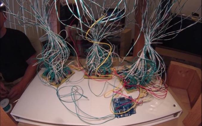
So here is the fully cabled IR matrix:
And here is the general schema:

Software
Arduino Nanos
Each Nano has an outer loop that counts to 14 and sets one of the "GND GPIO" low in turn, while the other 13 are high. Inside this loop, the nano basically performs 2x7 measurements in a loop which goes:
- measure row <n> (ambiant level)
- set "VCC GPIO" high on row <n>
- measure row <n> again (reflection level)
- set "VCC GPIO" low on row <n>
Then
- it compute the delta (reflection - ambiant)
- if the Nano is master, it sends a "start of message" byte, then the column number (0-13), then the 7 deltas, then listens and waits until it gets a "end of message" emitted by the slave
- if the Nano is slave, it listens until it gets a "start of message", counts the 7 deltas emitted the master, then sends its own 7 delta plus a "end of message" byte
Then the Nano starts again with GND active on the next column.
One interesting thing to note is that the only sync between the two Nanos is the serial message. Even though one of them actually drives the I/O expander, the fact that they run the same code guarantees a high precision in timings as they run in parallel. The only time when code differs (the sending phase), I added a delay (measured by experience) on the slave to accomodate the time it takes the master to receive and detect the "end of message" byte.
Fun fact: one might wonder how we can be sure the Nanos are kept in sync, particularly regarding column numbers. Indeed, in case there is a temporary loss of connection, or one of the Nanos restarts, or after any condition happens that requires a resync, we have no guarantee that the outer loop will be at the same column number in both Nanos. Surprisingly, that doesn't really matter as long as the master is the one controlling the I/O expander. Indeed the only thing that matters is that the number sent by the master in the message is the number of the actual column powered by the expander. As the slave does not write the column number in the message, if it doesn't drive the expander either, the column number the slave "thinks" it is on does not matter : it just performs 2 measurements per row and returns their difference.
One more thing regarding the Arduino Nano: the Library to control the I/O expander was found in this thread.
Here is the sketch I used.
Raspberry Pi
In Glediator, a Generator is the primary class that renders contents. Generators can then be combined together to create Scenes, which can then in turn be combined to create PlayLists.
The basic idea is to create a Generator that takes the serial input from the Nanos, calibrates their values, and then renders them as a greyscale level on a matrix. After that, one can for example combine that matrix with a Rainbow Generator with a "multiply" operation, so that output is dark where no obstacle is "seen" by the IR, and rainbow-colored where an obstacle is detected.
Unfortunately, Glediator is not open source as I said, and has seen no evolution in the last two years. However, The great advantage of Java for hackers is that it is easy to change the behaviour of a Java program by overriding classes. So I quicky analyzed Glediator's classes to see what could be done, and I came up with a way to add new "generators" (much like extensions are added to browsers) by just giving replacement classes higher priority than the original ones in the classpath, and leaving the original Glediator distribution untouched.
I tried contacting the authors - SolderLed - several times to propose them to include those changes but got no reply. So I guess contributions are not welcome, or they just leave the project as abandonware . In that case I hope SolderLed won't mind if I share the changes here.
For those interested, here is the code I sent them as a proof-of-concept. It contains the original Glediator v2.0.3 + a patch that overrides 4 Glediator classes to recognize "pluggable" generators + two new sample Generators: the first is a dummy "Uniform" color generator which is similar to the "Black" generator but with any color, and the second one is a "Game of Life", just because... you know.
Here's a demo with those two :
Next step: The Glediator generator reflecting exactly the values received from the IR matrix as a greyscale value (ok, there is mirroring mistake which was fixed later on). As you can see, it worked pretty well first time, but note that this is the ideal case, without white cardboard separators and translucent acrylic. Keep an eye on the screen at the right:
Note how the different cells have different values when nothing is in front of the leds. This is partly due to component dispersion, but also to the imprécisions in my build regarding led orientation. If they emitter and receiver are more or less "in front" of each other, the quantity of received IR can greatly vary, hence the calibration phase. The difference is made even less visible once the separators, and more importantly the translucent acrilyc plate are in place, so we need to amplify that difference, and that is the goal of the calibration phase too.
That calibration is thus done by determining low and high thresholds for each cell, and performing a linear interpolation in between, as follows:

So the generator is first put in calibration mode, where it records the extreme "high" and "low" values observed for each cell, and stores them in two arrays. When exiting calibration mode, all incoming values will be "scaled" according to those extreme values. To check how it behaves, I developed the following UI:
With this approach, results are much better, even with the full separators and top plate:
However, this greyscale version doesn't give good results when combined with other effects using a "multiply" operation, because calibration is made with white paper laying flat on the table, which produces much higher reflection than average skin waved at the surface, resulting in a very dim image. As a first measure, a "threshold percentage" was added to convert this greyscale to binary ("black or white") values. Of course, while this percentage is a general setting, the actual value of the threshold varies from cell to cell according to the calibration. For example, a 30% threshold would be computed as follows on two cells:

This is now much better:
As a last improvement, I replaced the unique threshold by a narrow linear interpolation from a low threshold to a high threshold. For example between 20 and 40%:

And the results are really cool :
Final bill
- Non-interactive version (see above): 70 EUR
- Raspberry Pi 3: 33 EUR
- IR leds: 8.5 EUR
- Straws: 2 EUR
- 2 more Arduino Nano clones: 4 EUR
- MCP23017 I/O expander: 1 EUR
- Flat cables with 2x7 pin connectors: 4 EUR
- Cables, soldering, resistors, perfboard, etc.: say 5-10 EUR
Total: 130 EUR (140 USD), or even less if you can recycle a power supply, a Raspberry Pi or a translucent acrylic plate.
For all the stuff there is in that table, I really think that's dirt cheap.
Final demo
pixel matrix + interactivity = ?
Tetris of course.
I say "Fucking awesome !"
Thanks for reading