CH923/CH925/CH926/CH928/ JY923/JY925/JY926/JY928 coin acceptor: Features and caveats
By Vince on 2017-02-25, 20:04 - Electronics - Permalink
I just finished testing this coin acceptor and I thought I'd write about it because it can be tricky and many sample codes I found on the net can lead to errors in coin identification.
What is it ?
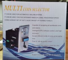
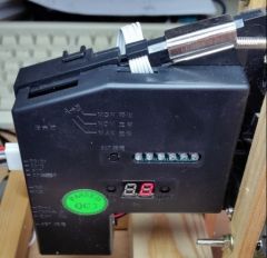
The CH92x (also sold as JY92x) is a cheap family of devices aimed at recognizing coins, to be used in vending or arcade machines. The variants differ in the number of kinds of coins they are able to recognize (3, 5, 6 or 8 kinds for CH923/JY923, CH925/JY925, CH926/JY926 or CH928/JY928, respectively). They have variable designs and variable packagings. Here's how I received my CH926:
How to use it ?
Setup
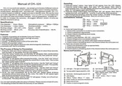
My package didn't include any documentation, but the setup procedure can be found online in several videos (like this one or this one) or in documents, such as the following one:
The procedure is a bit tedious but works seamlessly. It consists of two steps:
1) configure the number of kinds of coins to recognize and, for each of them, How many of samples will be used for learning that kind of coin, the number of Pulses to generate when that kind of coin is detected, and the Filter precision for that kind of coin (1=restrictive, 30=loose).
| Do not forget to power off the device after this step |
2) feed the coin acceptor with as many samples as you have defined above for each kind of coin. It is advised to use a minimum of 15 coins for each kind to cover all variations. The device accepts up to 30 samples per kind. Of course, it is useless to sample the same coin several times...
| Although the documentation above says the working current is 65mA, the peak when detecting a passing coin is well above 100mA, so make sure your power supply is able to provide current peaks. I suggest a 1A power supply. |
Operation
Once configured, for each recognized coin, the device produces a train of <n> pulses on the "COIN" line, <n> being dependant on the kind of coin as configured in step 1 above. The fourth (grey) wire is labelled "COUNTER" on the device and in some documents, but I could not determine its function. It looks like it's in high impedance all the time...
| Many uses on the net show the COIN line directly connected to an Arduino or RPi input. On my model, the COIN line can be in two states : floating or connected to ground, so a pull-up must be connected to it in order to measure voltages. It can be an external pull-up resistor, but it's much simpler to configure the GPIO it's connected to as INPUT_PULLUP of course. It may be worth checking that it's also the case for you because if your model has an internal pull-up, it could fry your microcontroller if you connect it directly |
Using a switch on the back, one can choose the IDLE state of the COIN line to be floating (normally open, NO) or set to GND (normally closed, NC). Most samples on the net use the most intuitive "NC" which makes pulses go up to VCC, but I personally chose NO to avoid wasting power in the pull-up resistor most of the time, which means my pulses are "going down" from VCC to 0V, but that does not really matter.
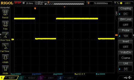
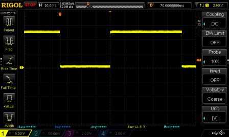
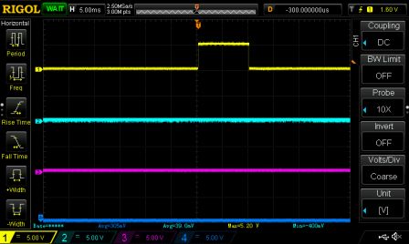
Each COIN pulse can have a different length according to the other switch at the back. The observed durations are as follows:
| Fast | 20ms/pulse |
| Medium | 50ms/pulse |
| Slow | 70ms/pulse |
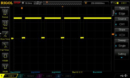
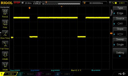
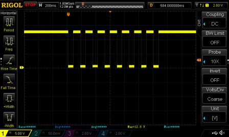
Each pulse is followed by a 100ms pause in idle state (no matter the selected speed setting). Here are a few traces for illustration:
- One coin configured as 4 pulses, "Fast" setting:
- Zoom on 1 pulse, "Fast" setting:
- Zoom on 1 pulse, "Medium" setting:
- Zoom on 1 pulse, "Slow" setting:
The "quick insertion" problem
Here's an example, when quickly inserting 2 coins in a row, with a pulse count of 4pulse/coin:
| As you can, there is no pause between coins, so there is no way to divide the pulse train for sure. What it means is that if you give arbitrary values to coins, such as, say, 1,2,3,4,5,6 then 2 coins of value 3 inserted quicky cannot be distinguished from 1 coin of value 6. |
This caveat causes a very common mistake in sample programs, and although some claim it can be solved by tuning delays, the trace above proves it's not the case.
For example, in this video. As the author says, he had difficulties getting to differenciate between coins and he relies on a timeout of 200ms to convert counted pulses to actual coins. That works pretty well if you leave time between coin insertions, but otherwise, you'll run into two issues:
- Issue #1: the program can be fooled by quickly inserting a 50p followed by a 10p, because the train of 4 pulses for 50p will take at least half a second (4 * (20+100)ms) and the 2 pulses for the 10p will be queued next to it, forming a 6-pulse train that will be seen as £2 => seller loses
- Issue #2: the program can also get stuck by quickly inserting two 50p coins for example, because the train will be 8 pulses long and that case is not handled by the code and those coins will get igored => customer loses
Let's take a look at another very popular example: http://timewitharduino.blogspot.be/2014/01/isr-based-sketch-for-adafruit-coin.html :
It also relies on a "time-out" of 200ms on the COIN line to count the pulses and determine which coin was inserted, and suffers similar issues:
- Issue #1: quickly inserting a $1 ("loonie") followed by a $0.25 ("quarter") will result in a train of 15 pulses which will display (and credit) $2 => seller loses
- Issue #2 is "somewhat" handled by a specific "Unknown coin" case. For example, quickly inserting two $1 coins will cause 20 pulses and make the code fall in the "Unknown coin" case. However, as there is no way to return coins, unless this alerts the store manager, they will be "lost". And even if the store manager gets an alert and looks at the logs, he won't be able to tell which coins were inserted to make 20 pulses: Was it 2*$1 or 4*$0.25 or another combination ?
The easy solution
The only way to solve the "quick insertion" issue is to forget about determining "coins" and focus on "value", which means choosing a number of pulses that is proportional to the face value of the coin. But if you choose a too small unit (e.g. 1 pulse/cent), then a $2 coin will trigger 200 pulses which is both impractical (the train will last for at least 24 seconds !) but also impossible as the device is limited to 50 pulses per kind.
| Consequently, with this device, it is impossible to reliably cover a range of coins where the largest value is >= 100 times the smallest one. For example, one will never reliably cover the full EUR or GBP range from 0.01 to 2 EUR/GBP, or even the full USD range from 0.01 to 1 USD.. |
Note that some documents also speak about an "AP mode" which seems to act as a divisor and only outputs one pulse after a threshold of <n> "internal pulses" (as configured with the P-setting) has been reached. I guess the goal is that if, for example, you sell items that are worth 50cents, you will only get a pulse every time 50 cents have been inserted (no matter if it's by 0.50, or 0.20+0.20+0.10, or 5x0.10, etc.). That reduces the number and length of pulse trains you have to handle, but does not fundamentally change the range limitation of course.
The sensitive solution is to cover a reduced range and give one pulse the value of the largest common divisor of all supported coins. For example, this popular Instructable covers 0.05 to 1 USD/GBP and maps 1 pulse to 5 cents. That code is safe and highly recommended.
I personnally chose the 0.10 > 2 EUR range, using 1 pulse for every 10 cents.
The drawback is that large values take a considerable amount of time to be decoded, and during that time, the feedback may be misleading: either you wait until the credit value is "stable" to display the credit (wait for timeout after last pulse to update display, not to count money) or you display a counter with slowly increasing value while pulses are being counted like in this video. The first can be freaky when you insert a big value and don't see any change for a "long" time, the second can be funny or unprofessional, depending on your point of view.
An intermediate solution is to start displaying a "hourglass" (or other animation) as soon as the first pulse comes in, and replace it with the total credit when it is stable. For example, here is a custom animation indicating that counting is taking place:
Here is the corresponding code : CoinTest_v5_with_LCD_anim.zip
The advanced solutions
The root cause of the issue is that the "pulse interface" is not really suited to the task. If it included a specified timeout between coins, the number of pulses per kind of coin could be greatly reduced. If the train was much faster (shorter pulses, shorter delay between them), then the "counting" phase would go unnoticed. This sluggish interface is particularly disappointing because the coin recognition itself is remarkably fast. Indeed, the 7-segment leds on the side of the device react almost instantly to coin insertion.
Solution 1 - SPI
One clever guy realized that the pulse interface could be dropped completely and replaced by decoding the values sent to the 7-segment controller via SPI. The C code is available but unfortunately, not much information is given regarding required connections.
I thought of doing the same but discoverd there were two other ways.
Solution 2 - Serial
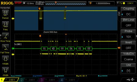
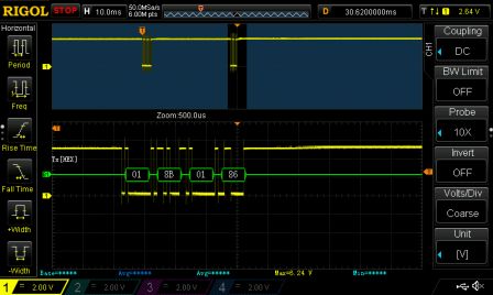
First, my CH926 has a debug port at the bottom.of the board. with a slightly unusual connector (6-pin JST PH with a pitch of 2mm). Following the tracks, one of the pins is directly connected to the serial TX pin of the main chip (a 20-pin STC12C5608AD). The serial is 19200 8-N-1 and the output on this port is 6 + 4 bytes each time a coin is inserted, with a long pause in between.
Here are the messages I observed :
| Coin type | 1st part | 2nd part |
|---|---|---|
| 0.10 EUR | 014D-008D-0188 | 018B-0186 |
| 0.10 EUR | 014A-008D-0188 | 018B-0186 |
| 0.10 EUR | 014D-008C-0188 | 018D-0186 |
| 0.10 EUR | 014B-0090-0188 | 018B-0186 |
| 0.10 EUR | 014E-0090-0189 | 018C-0186 |
| 0.20 EUR | 0147-0063-015F | 018C-0186 |
| 0.20 EUR | 0146-0068-0164 | 018C-0186 |
| 0.20 EUR | 0149-0067-0164 | 018C-0186 |
| 0.20 EUR | 0147-0063-0162 | 018D-0186 |
| 0.20 EUR | 0147-0063-0162 | 018C-0186 |
| 0.50 EUR | 013E-004E-00FC | 018D-0186 |
| 0.50 EUR | 0141-0054-00FC | 018C-0186 |
| 0.50 EUR | 0141-0051-00FA | 018B-0186 |
| 0.50 EUR | 0141-004E-00F8 | 018D-0186 |
| 0.50 EUR | 013C-0051-00FC | 018C-0186 |
| 1 EUR | 0167-006C-015F | 018D-0186 |
| 1 EUR | 0168-006E-015D | 018D-0186 |
| 1 EUR | 0168-006C-015F | 018D-0186 |
| 1 EUR | 0166-006F-0158 | 018D-0186 |
| 1 EUR | 0169-007A-015F | 018D-0186 |
| 2 EUR | 017B-004E-0132 | 018C-0186 |
| 2 EUR | 017C-003F-0138 | 018D-0186 |
| 2 EUR | 0179-0042-012F | 018C-0186 |
| 2 EUR | 017B-003E-0135 | 018C-0186 |
| 2 EUR | 0179-0042-0132 | 018C-0186 |
| 0.05 EUR | 0128-000F-0159 | 018D-0186 |
| 0.05 EUR | 012C-0015-0159 | 018D-0186 |
| 0.05 EUR | 012C-0014-015A | 018D-0186 |
| Plastic token | 018C-018D-018D | 018B-0186 |
| Plastic token | 018C-018C-018D | 018B-0186 |
| Plastic token | 018D-018C-018C | 018B-0186 |
Although I have no idea what the individual values represent, one can notice that they all range between 000Fh and 018Dh, and that they are very similar among coins of the same kind, so those data are probably raw measurements from the sensors sent out for debugging purpose.
I think that with these data, the "coin recognition" algorithm can (and must) be re-implemented externally. Unless you are dissatified with the algorithm in the coin acceptor, this has little use, because although we could recognize more kinds of coins, there is no way to make the device actually "accept" more coins (activate the solenoid to allow the coin in and not reject it). Maybe that can be done by sending messages through the Tx pin which is also available on the connector, but the protocol is unknown... Otherwise, you can drive the solenoid yourself of course, but taking a step back, you are getting closer to building your own coin acceptor...
Solution 3 - Led
It's not the case for all devices of the CH95x family, but mine has a series of 6 leds along its side:
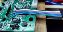
Each time a coin is recognized, the corresponding led flashes briefly, so as a very raw interface, simply reading the values of the leds immediately gives the kind of coin that was just recognized. Technically, it was rather simple to connect to those leds: The case can be opened with simple screws (one of them was under the "Passed QC3" sticker) but I had to unsolder the large coil above (because the coil itself is glued to the coin path) before I could reach the "front" of the PCB. I then soldered 6 wires to the anodes of the leds (the GND is common with the power connector on the back) and hot glued them in place. The setup looks like this:
Basic spying on those wires showed that for each recognized coin, a pulse of 150ms is flashed on the led. Cool. ... but unfortunately, there are some glitches that have to be eliminated.
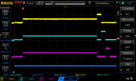
- First, upon powering, the pins are in high impedance, then the boot sequence of the CH926 flashes each led in turn for 10ms (here with leds 1-2-3):
These issues can be solved with pull-down resistors (1K to 10KOhm) and with a delay in the setup() of the Arduino, which should ignore the boot sequence if the power supply is common to the coin acceptor and the Arduino.
- Second, for an unknown reason, leds seem to randomly flash during 10ms once every minute or so, even when no coin is inserted. Here is a capture of such a "flash":
To solve this issue, the software has to reject all flashes shorter than a given value. I implemented the software using pin change interrupt and here is the result:
Here is the corresponding code : CoinTest_v6_Led_decoding.zip
Conclusion.
The CH92x is a very reliable device but it requires careful software design to avoid its pitfalls. If you don't want to modify the led interface, I advise you to stick to a proportional count of pulse with respect to the coin value, and use an animation to give feedback to the user while you count the pulses. If you want the fastest response and have a model that has individual leds for each kind of coin, I think it's the best way to interface it.
Have fun !
