Introducing the WAHOOcorder
By Vince on 2017-06-05, 15:44 - Electronics - Permalink

tl;dr
What ?
- A set-top box modified to add Wi-Fi
What's special about it ?
- Bidirectional interactivity from a browser
- Advanced features such as user-firendly search interface
- Bidirectional integration with existing operator website
- 5 EUR (5 USD) modification
Demo Video
Jump straight to the features to skip the setup presentation.
Note: A French-audio version is also available here.
What is a WAHOOcorder ?
Well, it started its life as a VOOcorder, a Cisco set-top box distributed since 2009 by the Belgian cable operator VOO. The VOOcorder is controlled by an IR remote or via its front panel. It has an integrated cable modem connecting it to the VOO back-end for TV Guide and VOD, but that's about it regarding interactivity, and in particular it has no Wi-Fi. Due to its age, it's now considered legacy and has been superseded by a new set-top box called .évasion, which works with a companion app and website that lets you zap or schedule recordings from your smartphone.
I thought it would be cool to add similar features to the good ol' VOOcorder by giving it Wi-Fi connectivity.
And so the Wireless-Activated Hacked VOOcorder was born, or WAHOOcorder in short.

What's inside.
As I don't have access to the STB firmware code, and I didn't want to perform irreversible modifications, I designed the additional features as a layer around the standard hardware.
Here are the added low level features:
- Brains: ESP8266. What else ?
- Control: The VOOcorder can only be controlled using a IR remote
- User feedback: Apart from the video overlay, the main user feedback is the front panel
- Monitoring: The VOOcorder also outputs debug information which can be retrieved from a serial port
All these features are presented in a bidirectional Web UI and API, presented both as a stand alone app as well as injected in the official VOO website.
Let's go into the details.
Brains.
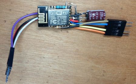
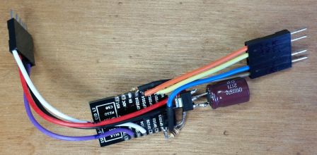
A simple AIThinker ESP-12F module is powered from the set-top box's front USB connector. The 5V is regulated to 3.3V by a AMS1117 followed a 220µF capacitor. Everything is assembled in "dead bug" style on the ESP-12F module, and is located inside the plastic front panel so that the WiFi antenna is out of the shielded case.
A small heatsink was later added because the ESP can get hot when enclosed. That heatsink also touches the STB metal case, further dissipating heat. As it is enclosed, the ESP is configured for OTA upload, but to avoid spurious flashing, a (hidden) button has to be pressed for the chip to reset in OTA mode.
Control.
By simply sniffing the signal using a version of IRrecvDumpV2 on the IR receiver, I identified a protocol similar (but not identical) to the NEC protocol . In particlar, it is mirrored (high in idle state, then 9000µs low, then 4400µs high, then 600µs low, then 1600 high, ...), and strangely enough, the first byte (address) of each message is not followed by a byte with all the bits inverted ("not address"), but the first two bits are just repeated without being inverted, so if address is 0b10000000 , the next byte should be 0b01111111 but it is 0b10111111...
Anyway, I decided to store the 32 bits as recorded and play them back untouched and it works perfectly. The codes for the remote keys are :
 0x80BFE11E for key 0
 0x80BF49B6 for key 1
 0x80BFC936 for key 2
 0x80BF33CC for key 3
 0x80BF718E for key 4
 0x80BFF10E for key 5
 0x80BF13EC for key 6
 0x80BF51AE for key 7
 0x80BFD12E for key 8
 0x80BF23DC for key 9
 0x80BF3BC4 for key POWER
 0x80BFF30C for key MENU
 0x80BF41BE for key EXIT
 0x80BF01FE for key VOL+
 0x80BF817E for key VOL-
 0x80BF39C6 for key MUTE
 0x80BF31CE for key BACK
 0x80BFBB44 for key FAV
 0x80BFA15E for key CH+
 0x80BF619E for key CH-
 0x80BF11EE for key INFO
 0x80BF53AC for key UP
 0x80BF4BB4 for key DOWN
 0x80BF9966 for key LEFT
 0x80BF837C for key RIGHT
 0x80BF738C for key OK
 0x80BFA35C for key GUIDE
 0x80BF5BA4 for key TV
 0x80BF19E6 for key RADIO
 0x80BFA956 for key HDD
 0x80BF6B94 for key VOD
 0x80BFB34C for key REW
 0x80BF8976 for key PLAY
 0x80BF0BF4 for key FFWD
 0x80BFB14E for key SKIP_BACK
 0x80BFE916 for key STOP
 0x80BFC33C for key PAUSE
 0x80BFC13E for key REC
 0x80BF916E for key RED
 0x80BF21DE for key GREEN
 0x80BF9B64 for key YELLOW
 0x80BF6996 for key BLUE
A GPIO of the ESP is connected in parallel with the IR receiver via a signal diode, and driven low to short the receiver to GND and emulate an incoming signal. This also leaves the original IR remote fully functional.

User feedback.
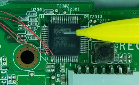
This was by far the hardest part. The front panel leds are driven by an Elan ePVQ6200 chip for which I couldn't find a datasheet, but I could find one for the ePVP6200 which looks similar. Its pinout revealed that it is controlled via SPI on pins 1 (DOUT), 2 (DIN), 51 (STB) and 52 (CLK), so I added wires to these pins to spy on the protocol.
Those wires were routed along with the IR "injector" to a connector at the end of the front panel board
A the time of development, the ESP8266 had no documented way yet of using SPI slave, but with the help of me-no-dev's SPI Slave library and explanations, I finally succeeded in decoding the messages sent to the Elan chip to update the leds.
The decoded protocol is as follows:
 msg = <command> <payload>
 where command is:
   0x08: repeated every 200ms, seems to be a heartbeat.
     payload is 0xFF 0xFF.
   0x54: update a 7-segment digit
     payload = <digit> + <value> + 0x00 + 0x00
     digit=
       80 for char 1 (left)
       40 for char 2
       C0 for char 3
       20 for char 4 (right)
     value=
       0bABCDEFGH with each bit corresponding
       to one segment, respectively
       <top><top_right><bottom_right><bottom><bottom_left><top_left><middle><dot>
   0xA4: update attributes1
     payload = <value1> <value2>
     value1 =
       0x70 for high display intensity ? (on)
       0x60 for low display intensity ? (standby)
     value2 =
       0x00 until now
   0x04: update attributes2
     payload = <value1> <value2>
     value1 =
       0x10 for power led red
       0x08 for power led green
       0x00 for power led off
     value2 =
       0xFF until now
 Notes:
   - the messages 54 and A4 always happen in bursts
     and the bursts are repeated every 3 seconds at least
     (when not in standby), in the following order :
     <digit 1> <digit 2> <digit 3> <digit 4> <digit 1> <digit 2> <digit 3> <digit 4> <attributes1>
   - the messages 04 happen only in response to a key
     press. They are not repeated regularly.
Side-note about using an ESP8266 as SPI slave.
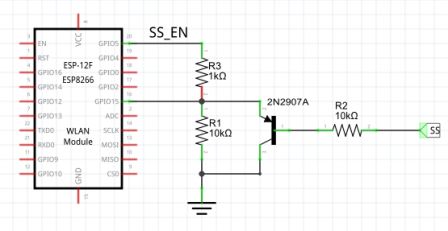
GPIO15 of the ESP must be low for the chip to boot normally, but GPIO15 is also the "Slave Select" PIN. In SPI slave mode, we have no control on that pin which comes from the master and, more often than not, the GPIO15 pin is high upon ESP reset, preventing it from booting. So I used a little trick: a separate ESP pin (GPIO5) acts as a "SS enable", and only activates the actual SS in the setup() function, when the ESP has fully booted. The schema is as follows:
Monitoring.
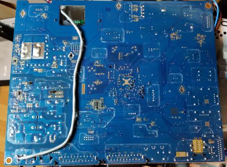
The STB has a 3.5mm jack at the back that is used for maintenance and outputs serial debug information. Connecting it to the ESP's serial port was trivial altough I took care to route the signal away from the mains power area of the motherboard.
Here is a video of the complete hardware assembly:
Software.
The software consists of 3 parts:
1) Code running on the ESP.
That code was written using the Arduino environment and ESP8266 core (the latest stable version at the time of development was 2.3.0).
It consists of several parts:
- The driver for the different hardware parts
- A generic web server for serving static files stored on the internal filesystem (SPIFFS)
- A specific URL exposing an API to emulate Remote Control keypresses. For example, calling /remote?keys=XT12^ emulates a keypress sequence of the keys eXit, Tv, 1, 2 and up arrow (^)
- A first websocket server for streaming of front panel led updates
- A second websocket server for streaming of serial debug logs
- A real-time parser of the incoming logs to extract interesting information, such as the ID (DVB triplet) of the current channel
I also included the Wifimanager library, OTA, as well as a call to send the DHCP-assigned IP address to my PushBullet notification app via PushingBox (because PushBullet's API can only be accessed using HTTPS while PushingBox allows HTTP).
Issues.
I encountered several crashes during development, but most were due to the webserver, which only supports one call at a time and has poor performance (although ESP8266 core version 2.4.0 or later should be optimized in that regard). I resorted to storing the CSS and images on an external website, and inlining all the javascript inside the html pages, so that only one page is loaded at a time, and it's now quite stable.
The SPI slave was a challenge, particularly due to the lack of ESP8266 chip documentation. The ESP is incredibly powerful, but SPI slave interfacing was mostly a trial and error thing and I couldn't have made it without Me-no-dev's help. His code is now included in the ESP8266 core, but even then, advanced features rely on register configuration for which documentation is largely missing. In the end, I was lucky that the front panel protocol only used a few messages because the ESP seems (?) to only understand a protocol of the form "command-address-data" (used for memory and some LCD chips), and command can only be one of master_read / master_write / slave_read / slave_write. If you design the protocol, that's no problem, but if you are faced with a SPI transmission that doesn't follow the "command-address-data" format, I frankly doubt the ESP will be able to handle it in all cases.
I also had problems with the serial Rx buffer overflowing when the processor was too busy, but I patched the ESP8266 core with this change (which should be in core 2.4.0 or later) and it solved the issue.
2) HTML pages and javascript code.
There are:
- Some static pages and links providing navigation between the features
- A page presenting a picture of the remote control, with links mapped to various areas of the pictures, calling the RC API
- A page presenting a picture of the front panel and opening a websocket connection to receive led updates. Coupled with a modified version of this Javascript 7-segment library to display changes in the UI.
- A page presenting a scrolling log of the debug information received from the dedicated websocket
- A page presenting the information parsed from the debug stream
- A page with a search form which performs the search on the set-top box by navigating the on-screen keyboard
3) Tampermonkey/Greasemonkey scripts.
Those scripts are used to modify VOO's "VOOmotion" website on the fly, and to allow it to control the STB. Namely:
- The home page was hacked to add a "setup" dialog window (e.g. to specify the IP of the Wahoocorder) and modify its VOOmotion logo to WAHOOmotion
- In the program guide, when selecting details of a program currently on air, a "Watch on Wahoocorder" button is added to allow a direct zapping to that channel
- In the program guide, when selecting details of a future program, a "Schedule on Wahoocorder" button is added to allow scheduling the record of that program by controlling the "manual recording" screen of the STB (including emulation of keypresses in SMS "multi-tap" style to enter program title)
- When activating "follow zapping" in the setup dialog, the site hooks to the front panel incoming stream via websocket and pops up the details of the program currently watched on television.
Note that using a browser for both search and manual recording circumvents the tedious process of entering text using a remote with no alphabetic keys. Particularly frustrating is that those two features use a different convention (virtual on-screen keyboard for search, multi-tap for manual recordings). Forget about those as required remote keypresses will be performed for you to fill the fields 
Conclusion.
This hack was made just for fun, but I was amazed at what can be performed with an outdated device by adding less than $5 in hardware.
The ESP8266 really deserves its place as the IoT king. I was stunned by the fact it could handle 3 distinct web servers while parsing two message streams without a hitch. If its documentation was more complete, no doubt it would step from IoT king to IoT emperor 
