Turning a Quick Charge 3.0 charger into a variable voltage power supply
By Vince on 2017-08-09, 22:33 - Electronics - Permalink
Disclaimer: the following refers to some cheap USB chargers which may not comply with local safety regulations and could pose a hazard. All you do is at your own risk and I cannot be held responsible for use or abuse of those chargers.
1. Introduction
A few months ago, I stumbled upon a Hackaday post presenting the QC2Control library by Timo Engelgeer (Septillion), which makes it very easy to turn a Qualcomm Quick Charge 2.0 compatible USB charger into a 9V or 12V power supply. I used that trick successfully to power a small project that required both 5V and 12V, and its simplicity made me want to dig a bit further into Qualcomm's Quick Charge technology.

As you may know, Quick Charge 3.0 adds the possibility to request any voltage between 3.6V and 12V (with 0.2V steps), and with some QC3 chargers available for less than 4 EUR, throwing in an Arduino clone and a few resistors make a very affordable way to power devices with custom voltages. Of course, for that price, don't expect top notch precision, protection, or power, but it is more than enough for most DIY projects, and the adjustable voltage can compensate voltage loss in long power lines (think wired sensors far from alarm system for example).
So I decided to try and see if QC3 could be controlled similarly to QC2. (Spoiler: it is the case, but required a few adjustments.)
For these tests, I used :
Here's the presentation of the test setup:
2. Test of the different chargers with QC2Control
I thought it was a good idea to start simple and use the QC2Control lib on the 3 chargers, so I uploaded the QC2Control's example sketch to the Arduino and observed the results with each charger in turn. QC3 chargers and battery packs should be backwards compatible, so I used the unmodified circuit and library. Here are the results:
The QC2 charger exhibits a strange behaviour: the QC handshake works and the voltage goes to 12V. It also successfully generates 9V. But requesting 5V then seems to completely reset the charger, with the output voltage dropping to 0V before coming back up to 5V. However, after the reset, the charger has left QC mode and a new handshake would be needed to get it back on track. Most probably it is a problem with the charger... any information is welcome.
QC3 chargers should have worked, but as you can see, the test fails with both the cheap one and the Anker one, and it took me some time to find the reason why....
USB power source identification and control
To explain, let's first go back to the basics.
Most of the communication between a portable device (PD) and a USB power source relies on the D+ and D- lines of the USB connection. Of course those USB data lines were not designed for signalling but for data transmission in a differential way: D- going down when D+ goes up (and conversely) and the receiving device subtracting D- from D+, so that if noise or spurious peaks happen during the transfer, they appear on both lines and the subtraction cancels them. But as a charger does not use the data lines, several standards or proprietary protocols were designed using those wires in a primitive way to identify the source or control it.
The first convention is that a charger starts with D+ and D- connected together (shorted), which is incompatible with the differential mode, and can thus be detected. If a PD is QC-compliant, it will set a voltage of around 0.6V on D+ for around 1.25s. If the USB power source is also QC-compliant, it will detect that voltage, remove the short between D+ and D- and connect a 20K pull-down between D- and GND. That is the QC handshake phase.
After that, the USB power source will start monitoring the voltages on D+ and D- and will act according to the detected levels.
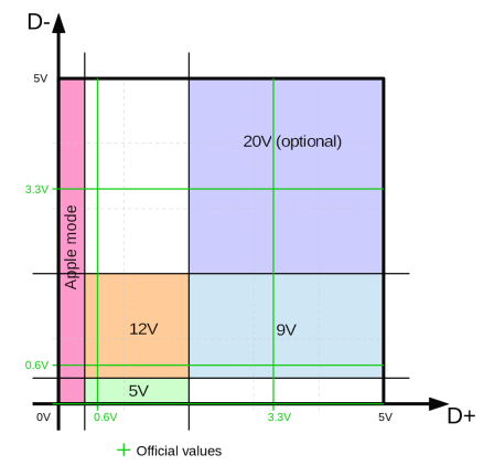
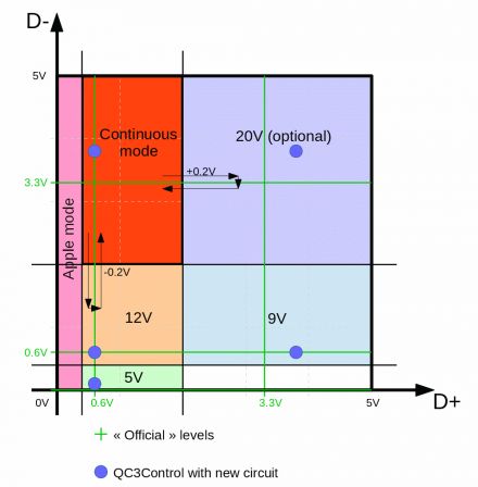
A very clear (in my view) definition of levels used by QC is a D+/D- graph inspired by this EOSMEM document, where areas define all QC2 "discrete" output values:
So what's the problem ?
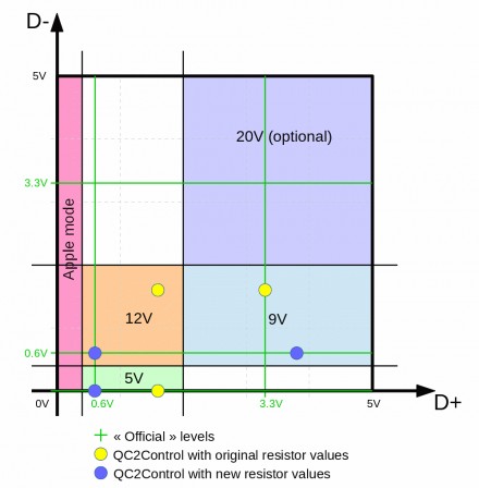
Qualcomm does not make Quick Charge specifications available publicly, but after some trial and error, it seems the failure was due to the voltages used for controlling D+ and D-. The original demo by Hugatry and QC2Control by Septillion were inspired by this TI reference guide which is based on the CHY100 chip. The CHY100 specifies voltage thresholds of 0.325V and 2V, and the resistor values were chosen to provide voltages around 1.6V for "low" and 3.3V for "high". While my Quick Charge 2 charger is happy with those voltages, none of the two QC3 chargers worked with a "low" voltage of 1.6V, so I changed the resistors to get the "low" voltage closer to 0.6V (value cited in most of the datasheets), while keeping the "high" voltage at 3.3V or above. Here are the values and corresponding voltages on the D+ side:

Note: if you want to fiddle with resistor values and compute the corresponding voltages, I made a LibreOffice spreadsheet that does exactly that. Change the values in the yellow and blue cells and check the graph at the bottom...
Graphically, here is a comparison of the voltages obtained with the original resistor values (yellow dots) and with the new values (blue dots). One can see that the blue ones are closer to the official values (intersections of green lines):
Here is the result with the changed values :
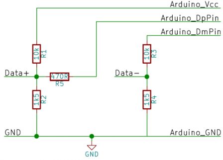
With those changes in place, QC2 modes worked with QC3 chargers as expected, so here's the circuit and values I'm using with QC2Control:
3. First test of QC3 mode
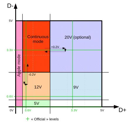
QC3 makes use of the area in the upper left corner of the graph that was not used by "discrete" QC2 voltages, and that area (in red below) is known as the "continuous mode":
Switching to continuous mode is as easy as selecting a QC2 voltage: after handshake is done, you set D+ to 0.6V and D- to 3.3V and that's it. No matter what the previous settings were, the charger is now in continuous mode (but the output voltage remains the same for now).
Once in continuous mode, you can send pulses "down" or "right" (see arrows) to respectively increment or decrement the output voltage by 0.2V.
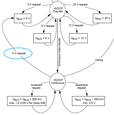
Leaving continuous mode and getting back to discrete mode can only be done by returning to the lower "5V" area (note that we're still in QC mode, so no new handshake is required). Consequently, there is no way to get directly from continuous mode to 9V, for example. This is very clear in figure 17 of this datasheet:
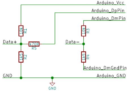
The original circuit, no matter the resistor values, cannot reach the continuous mode quadrant as the voltage on D- must be around 0.6V when Arduino\_DmPin outputs 5V. So my first attempt used a slightly modified version, connecting the lower resistor of the D- divider to a third pin of the Arduino (Arduino\_DmGndPin) instead of GND so it can be made floating. That way, D- can be pulled up (to be precise, when the pin of the lower resistor is left "floating", the upper 10K resistor connected to the pin outputting 5V balances with the 15K pull-up Inside the charger, so the actual level on D- is around 3V).
The resulting 3-wire "legacy" circuit is thus:
The code required a serious rework, but after a few cycles, I think I can say it is a success  :
:
Circuit improvement
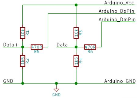
That was quite satisfying, but I thought it would be cool to get rid of the need for that third pin, so I modified the circuit again and duplicated the D+ configuration to the D- side: a divider between VCC and GND plus a third resistor to the Arduino "DM" pin. Now, outputting 5V on Arduino\_DmPin, a voltage of 3.3V (or a bit more) can be set on USB D-. Here are the target levels (blue dots):
And again, after some coding, I could make it work.
Here is the corresponding 2-wire "recommended" circuit:
4. The QC3Control library
To design the Library, I started from the QC2Control project, which is easy to understand and has a clean API, and forked it to add QC3 features. In the end, most of the implementation has been rewritten to work in milliVolt internally, but the API should be fully backwards compatible, with a twist.
You can find the code of QC3control on Github here.
The twist is that while set5V(), set9V() and set set12V() have the exact same behaviour as in QC2Control and request discrete 5V, 9V or 12V mode, **But** setVoltage() now always uses QC3 continuous mode to reach the requested voltage (which is now a 'double' to support decimals). It means that setVoltage() cannot be used with a QC2 chargers anymore contrary to the 3 first functions, but it also guarantees that switching voltage using setVoltage() will always be made in a smooth (monotonic) way. For example, if voltage is now 10V and you call setVoltage(12), a quick ramp will increase voltage by 2V in 10 steps. On the other hand, if voltage is now 10V and you call set12V(), the charger first has to leave continuous mode by switching to 5V (see state diagram above) before requesting discrete 12V, which causes a brutal voltage drop. Performance is not affected in a major way by the ramps because each increment (or decrement) of 200mV only takes 2ms, while the discrete mode change to 5V takes 60mV before requesting the new voltage (this might be slightly reduced but I played it safe). In the end, the choice of mode is left to the programmer using the library.
4 more methods were also added:
- incrementVoltage() and decrementVoltage() to request a single step of 200mV up of down
- setMilliVoltage() and getMilliVoltage() are identical to setVoltage() and getVoltage() but the unit is milliVolt and values are thus integers instead of double.
Warning about partially compliant chargers
In my tests, I noticed that the cheap QC3 charger did not go down to 3.6V but instead it stopped at 4V and ignored further "decrement" requests. The fact that setVoltage() now uses relative steps instead of absolute jumps means that such offset can impact the full voltage range if you only use setVoltage().
For example, with such a charger, if right after start you call setVoltage(3.6) then setVoltage(9), the actual voltage will reach 9.4V. That's because setVoltage(3.6) issues 7 decrement requests ((5-3.6)/0.2 = 7), of which the last 2 are ignored, stopping at 4V, then setVoltage(9) issues 27 (=(9-3.6)/0.2) increment requests, which causes the voltage to be increased by 5.4V, to 9.4V.
The same kind of offset could happen if spurious peaks are detected by the charger, so it is advised to limit the use of repeated continuous mode requests to fully validated setups.
Note: Why keep 2 circuits and 2 implementations ?
In other words: why not get rid of the legacy circuit?
The 3-wire "legacy" circuit is kept because it adheres more precisely to the QC specification. Indeed, according to the spec, the handshake should only drive the D+ wire while the D- wire is left floating (high impedance) until the charger has removed the short between D+/D- and activated a 15K pull-down on D-. This high impedance state can be achieved by letting the resistors of the D- divider "unconnected" (or connected to Arduino pins configured as inputs). That is what the library does in "3-wire" configuration.
The 2-wire "recommended" circuit has no way to leave D- floating because the divider is always connected to VCC and GND. During the phase when the charger has D+/D- shorted, having both dividers producing 0.6V gets unnoticed by the charger (because they are shorted anyway). However, when the short is removed, D- is expected to immediately be pulled down to 0V by the charger's internal 20K resistor, but the divider prevents that due to its lower (10K/1.5K) resistor values, and D- remains around 0.6V. The library thus forces D- low after a delay by setting DmPin to 0V, and that gets recognized by both my chargers as an "acknowledge" of the QC handshake.
If your QC3 charger refuses to generate anything other than 5V with the recommended circuit, it may be due to the fact that this "low" pulse does not come right after activation of the 15K pull down. In that case, please try with the legacy "3-wire" circuit, using the 3-parameter constructor, and let me know 
5. Demo
OK, so what can we do with a programmable QC3 charger ? Maybe draw something ? How about this:
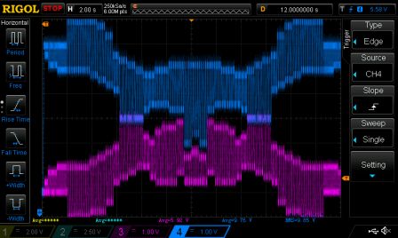
I indend to make a blog post for the making-of of this logo, but in the meantime, here is the proof this was really generated by a QC3 charger  :
:
6. Update
User allenchak asked if it was possible to use QC3Control with a 3.3V microcontroller, and after a bit of fiddling, I suggested and he confirmed it works and just requires other resistors.
Here are values that work on the 2-wire "recommended" circuit. Tested with a Pro Mini 3.3v and a ATtiny13A powered with 3.3V:
R1 = R3 = 4700 Ohm
R2 = R4 = 1500 Ohm
R5 = R6 = 100 Ohm
