RefloWaffle: A dirt cheap reflow oven - the Belgian way
By Vince on 2020-11-08, 12:00 - Electronics - Permalink

"For her a Moulinex, for him delicious meals"
Though I don't do many PCBs, I guess every hacker must have a reflow oven. So this is a project I've been pursuing on and off for nearly 4 years:
A small, portable, and dirt cheap (less than $25) reflow oven.
After a few tests with a traditional electric oven recovered from the trash, I concluded its thermal inertia was so high it would require massive modifications to achieve anything close to a decent reflow profile, and as I didn't feel like spending much money on a large oven, I looked for a better way.
And I think I found it. Read on for more...
The "oven"
Although Belgium's national dish is fries (mistakenly called "French fries" in English), we are best known abroad for our waffles. And coincidentally, my wife had just decided to replace our old waffle toaster because its closing clip was broken, so I wondered if I could transform it into a reflow oven.
Of course large PCBs would not fit, but the relatively small size of that toaster would also make it easy to put it away in my small lab. Plus, it has both top and bottom heating elements, and the small volume limits energy losses.
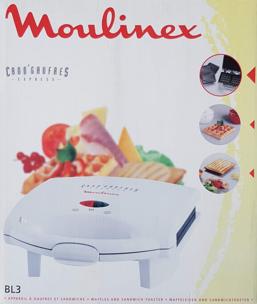
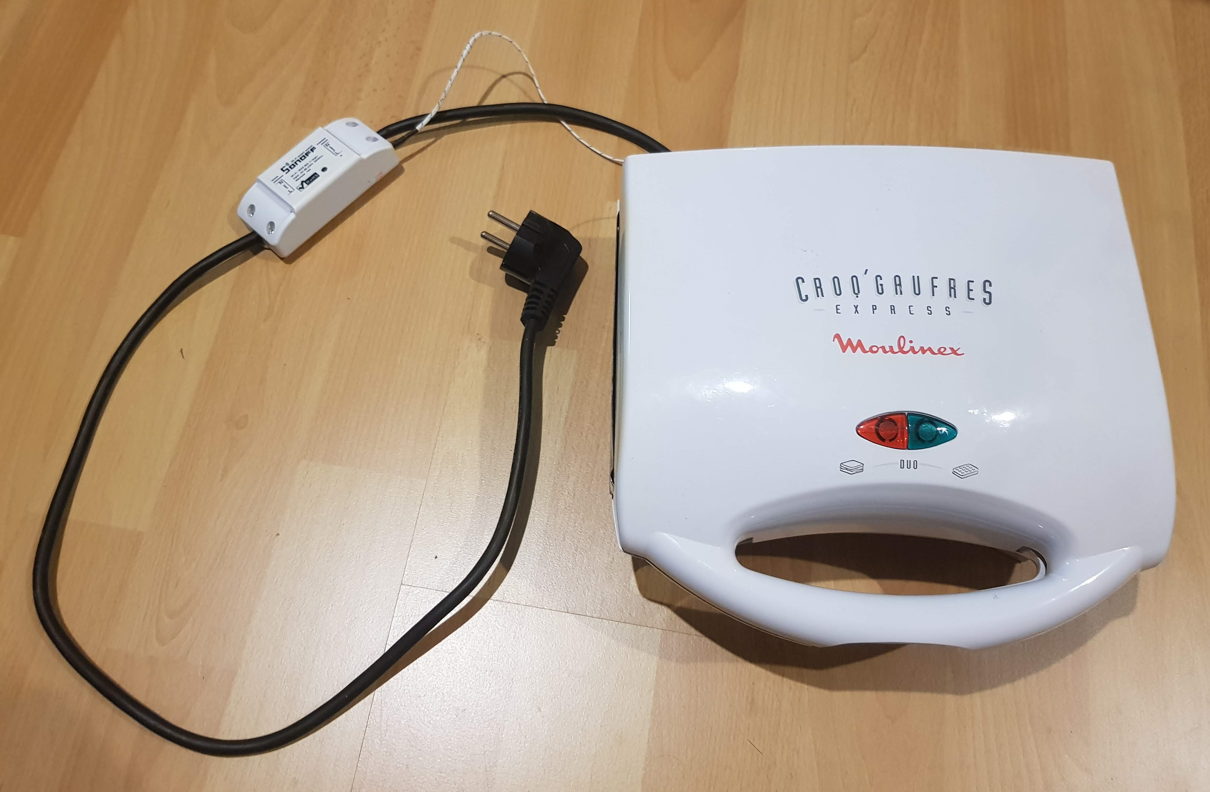
 The toaster in question is a "Croq'Gaufres Express" by Moulinex.
It has removable hotplates and is limited to 700 Watt, which is not much but I thought it was worth a try. I quickly put together an Arduino with a MAX6675 and K-type thermocouple to monitor the temperature in different conditions, but it was clear that with the hotplates, its inertia was too high, taking around 5 minutes to reach 150°C while most reflow profiles require around 1 or 2 minutes for that ramp.
The toaster in question is a "Croq'Gaufres Express" by Moulinex.
It has removable hotplates and is limited to 700 Watt, which is not much but I thought it was worth a try. I quickly put together an Arduino with a MAX6675 and K-type thermocouple to monitor the temperature in different conditions, but it was clear that with the hotplates, its inertia was too high, taking around 5 minutes to reach 150°C while most reflow profiles require around 1 or 2 minutes for that ramp.
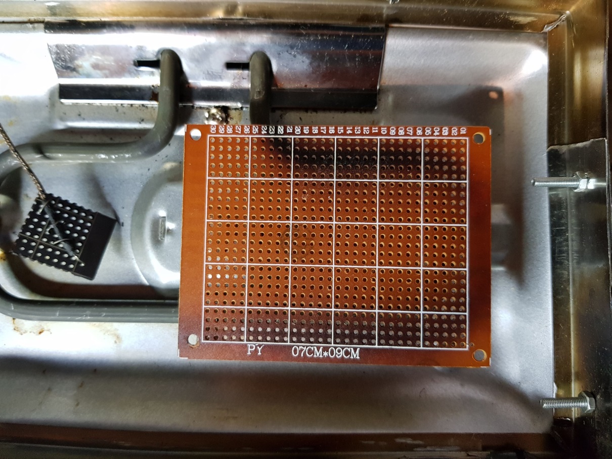
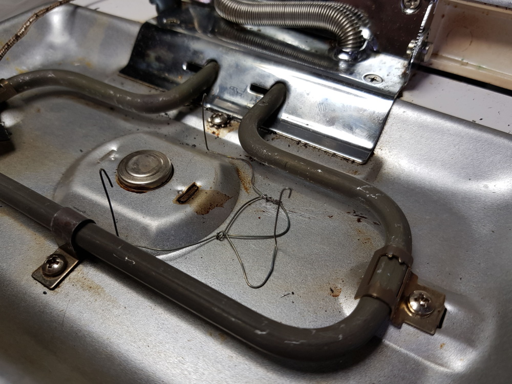
I then tried to reduce thermal inertia by removing the hotplates and the results were much better. However, the heating elements were then so close to the PCB that they made it overheat, leaving a burned trace on the PCB just under the element (see picture below). Even if high temperatures are not dangerous for the PCB itself, it meant the components would not be evenly heated, and that's not good.
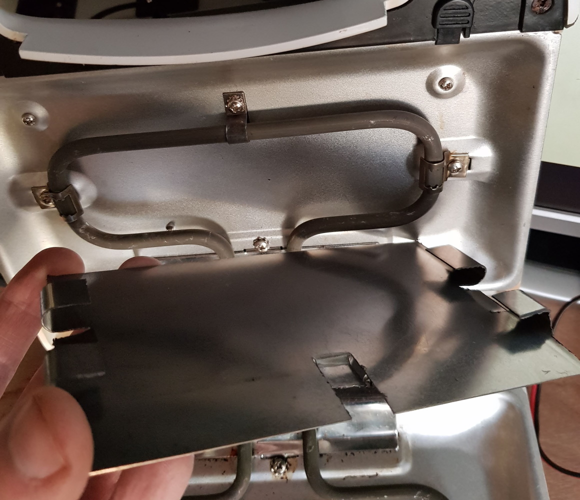
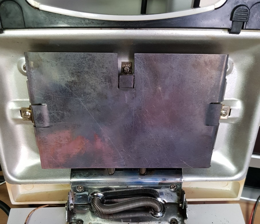
So I needed a way to distribute the heat, and what better heat conductor than a copper plate ? As SMD components are only on the upper side of the PCB, I bought a 0.5mm copper plate and placed it on top, wrapped it around the heating element, and with that set-up, the PCB became evenly heated within a reasonable warm-up time.
I also quickly cut and bent a piece of scrap metal to create a frame and fill the gap left all around the frame by the now removed hotplates, then used some of hard wire as support for the boards and attached the thermocouple to a piece of PCB to simulate a similar thermal inertia,
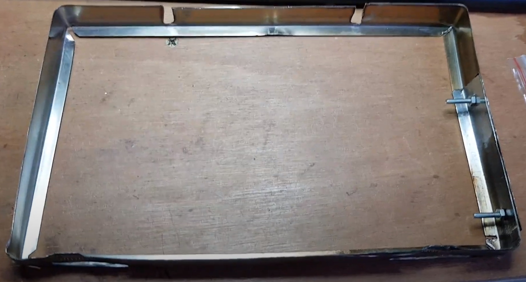

Hot waffles anyone ?
Controller hardware.
Many people will tell you that heating elements should be controlled using a solid-state relay, because traditional relays wouldn't survive long to being constantly toggled on and off.
I decided to ignore that advice however because, you know, relays are dirt cheap :-). Also thanks to the thermal inertia, it's not needed to use a high frequency PWM - and I settled on a 2-second cycle. So a 10-min reflow cycle would require at most 300 on/off cycles. Plus, I only need to reflow once in a while, so I figured the relay would last long enough.
In the the dozens of reflows I performed until now, the relay didn't show any sign of wear. Maybe one day it will fail, but as it will never run unattended, I'm not really worried...
Hardware attempt #1
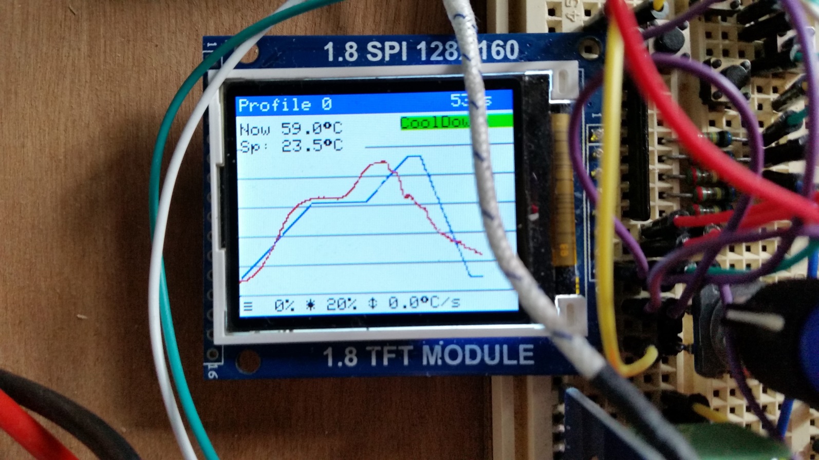
My first breadboard controller prototype used an Arduino Nano clone, a cheap relay module, a 160x128px LCD and a rotary encoder, and it ran a modified version of the Reflow Oven Controller code by Karl Pitrich and Ed Simmons.
I intended to use a small Hi-Link 220v to 5V converter. However, as soon as the Arduino was connected to that converter, it randomly reseted, probably due to spiked caused by the relay, so I guess it would have required a good filtering stage, and I'm not good at that.

Plus, I don't have a 3D printer, so finding a suitable case was also on the to-do list. The project remained in that state for 2 years, serving its purpose from a a 50% breadboard with workbench power supply, 50% relay board powered by the Hi-Link setup.
Hardware attempt #2
But a few months ago, I finally decided I had to finish the project and it struck me that I had the perfect controller hardware sitting on my shelf for months:
What device includes a microcontroller, a power supply and a relay, in a small box and costing less than 5 bucks ? A Sonoff module, of course !
And a web UI would also be much more user-friendly than a tiny screen and a rotary switch.
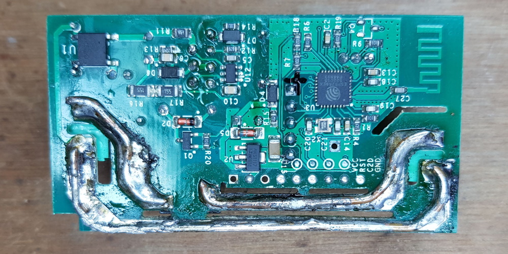
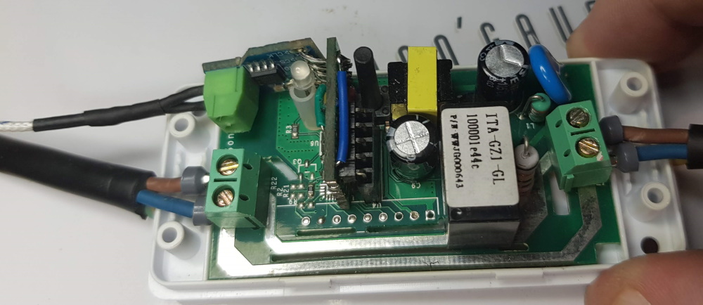
I only had a Sonoff R1, and as it is known for its weak mains PCB tracks, I reinforced them with some 1.5mm² copper wire to make sure they didn't overheat. I also soldered the header required for flashing my own firmware, and split the power cable of the toaster (keeping the earth wire directly connected).
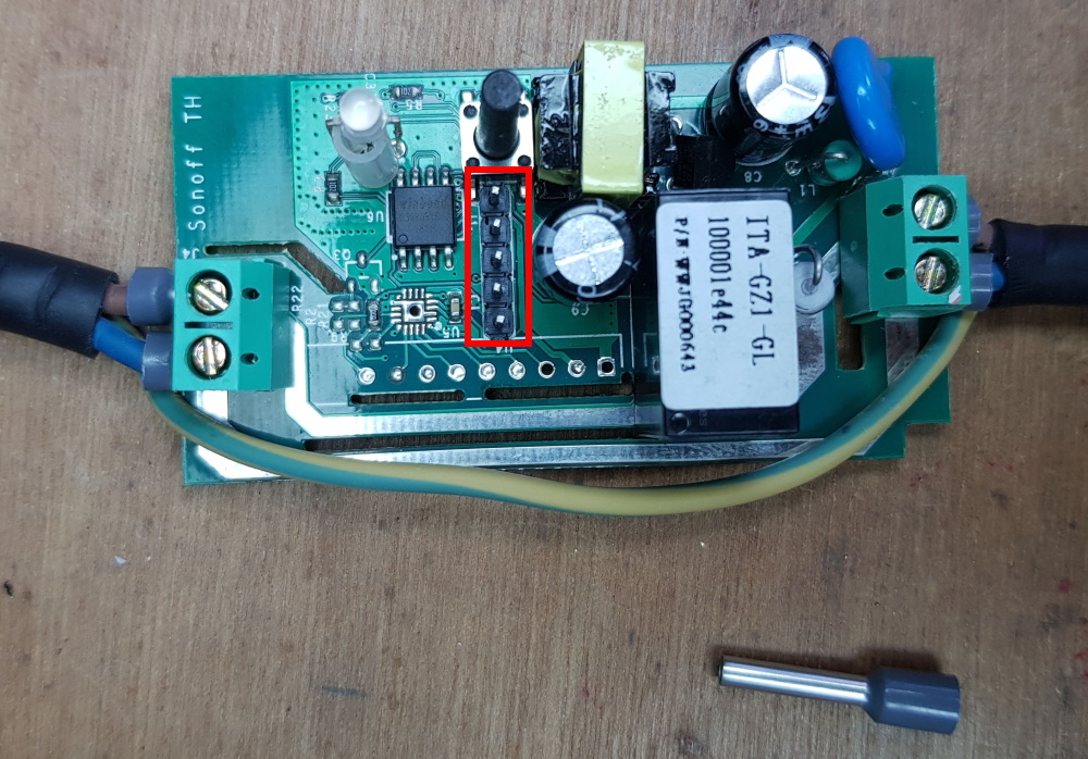
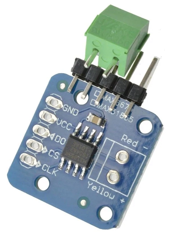
The only issue with the Sonoff is that very few GPIOs (Rx/Tx and IO2) are broken out on the header, and the 31855 (or 6675 btw) K-Type thermocouple converter is SPI and require 3 pins, so the only way was to repurpose the Rx/Tx, which means that once the temperature sensor is connected, there is no way to perform serial monitoring anymore...
With that idea in mind, all that was needed was to fit a thermocouple converter inside the Sonoff case. I figured I could trim a 31855 breakout board with a Dremel to make it fit, with two right-angle turns to fit the connector:
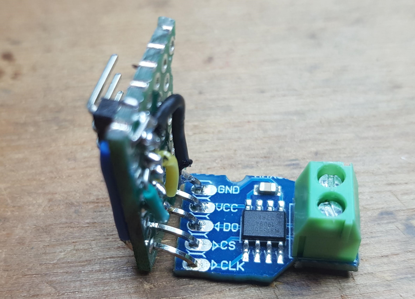
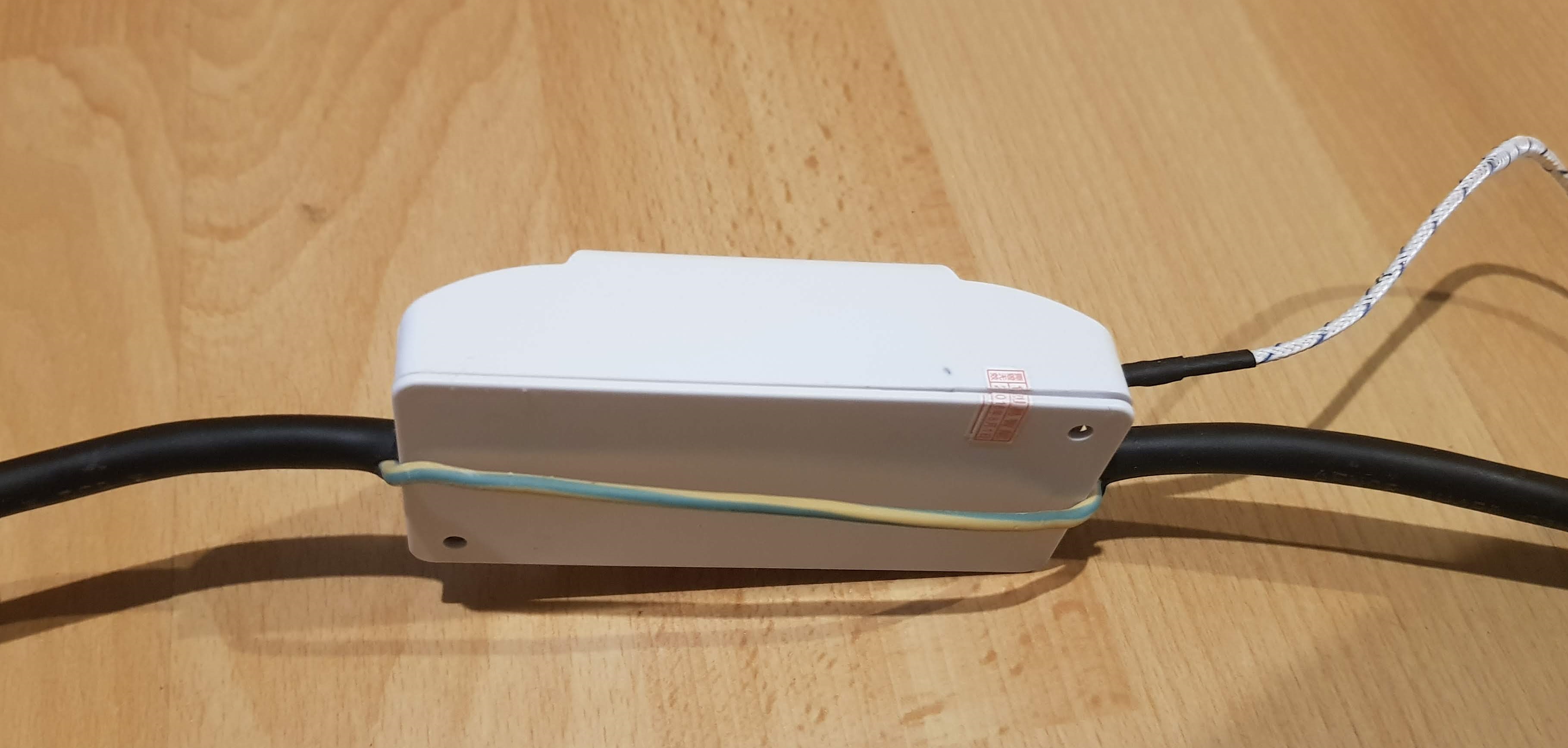
Everything fits inside the Sonoff (just had to dremel out a small path for the thermocouple wire), except the earth wire which I left running separately:
The software for the controller.
![]() At the heart of the reflow process is a state machine that switches from state to state: idle -> heat to reach the "soak" temperature -> wait for soak temp. to be reached -> "soak" -> heat to reach the "peak" reflow temperature -> wait for peak temp. to be reached -> "peak" -> slowly let the temperature fall -> forced cool down.
Note that while heating is controlled by software, cooling down is left to the operator by slowly opening the lid and trying to stay as close to the desired curve as possible - funny game by the way.
Different PID controls are used throughout the cycle, along with some delays and a bit of empiric methodology
At the heart of the reflow process is a state machine that switches from state to state: idle -> heat to reach the "soak" temperature -> wait for soak temp. to be reached -> "soak" -> heat to reach the "peak" reflow temperature -> wait for peak temp. to be reached -> "peak" -> slowly let the temperature fall -> forced cool down.
Note that while heating is controlled by software, cooling down is left to the operator by slowly opening the lid and trying to stay as close to the desired curve as possible - funny game by the way.
Different PID controls are used throughout the cycle, along with some delays and a bit of empiric methodology 
As the Sonoff is based on an ESP8266, the Web UI could be polished and made much more user-friendly than anything I could have done in hardware. Here is how a full reflow 11-minute session looks like (feel free to speed up or skip through the video of course):
The reflow graph is updated in realtime using a WebSocket and drawn using the HighCharts Javascript library, which makes real-time monitoring of the process very easy. But apart from that, here are additional features of RefloWaffle:
- the reflow sessions are stored on the internal filesystem of the ESP with their timestamp (no real-time clock, just a web request :-)), available for future reload or ready to be downloaded as CSV
- all profile parameters (e.g. temperatures and delays) are editable from the Web GUI and stored in a JSON config file
- the Wifi configuration is done via a captive portal using the excellent WifiManager library. The controller can then be found on the local network as http://reflowaffle.local using mDNS.
- the internal led of the Sonoff indicates the status of the process (misc flashes during boot-up, off when idle, steady during a reflow cycle), and in case you don't have a computer or smartphone (??) the Sonoff button can be used to start or stop a reflow cycle, or to reboot the Sonoff with a long press.
- real-time logging is redirected to a window, which is even easier than serial logging.
- plus session and file management
Total cost.
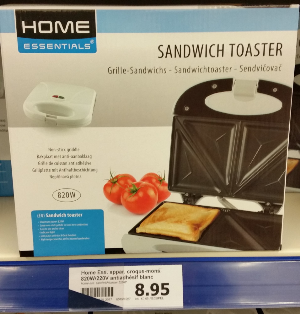
- Toaster: I got it for free but a new one can be found for less than 10 EUR at hard discounters:
- Copper plate: (3.26 EUR incl. shipping on AliExpress)
- Sonoff module: (5.10EUR, free shipping on AliExpress)
- K-Type thermocouple: (0.73 EUR, free shipping on AliExpress)
- Max31855 breakout board: (1.71 EUR incl. shipping on AliExpress)
Grand total: 19.75 EUR or around 24 USD
Conclusion.
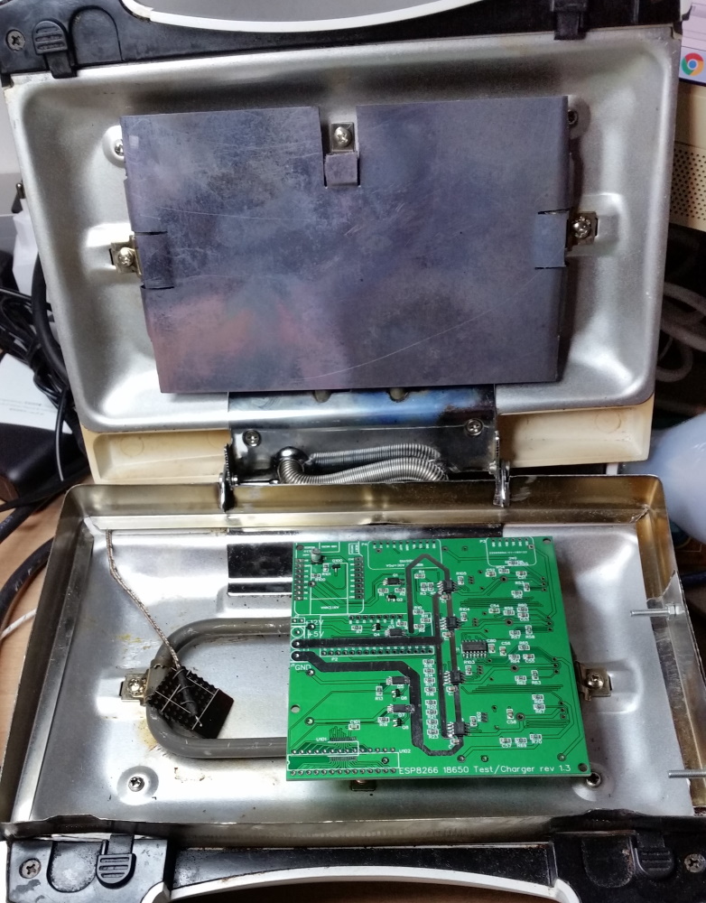
Here is how the final setup looks like:
Small, portable, effective, and dirt cheap. I think this fits the bill pretty well
Happy hacking !
Note: if you are having trouble falling asleep, here is the full video of a "proof of concept" reflow cycle (yes, I should have opened the lid much sooner).