Introducing CHAI - a CAME gate controller to Home Assistant Interface
By Vince on 2024-01-20, 14:09 - Electronics - Permalink
I have a parking gate with a Came BXV controller and wanted to fully integrate it with a home automation system. Using a good old ESP8266 and ESPHome, I can now exactly control the movements from Home Assistant, get feedback of the actual gate position and state, and control it remotely or set-up alarms in case it stays open for too long for example.
So let me introduce CHAI - a CAME gate controller to Home Assistant Interface
Intro
A few years ago, I installed a sliding parking gate with a Came BXV controller. I always thought it would be great to integrate it with a home automation system, for the following reasons:
- The provided RF remote control has a limited range and you can never be sure the command has been received when you press the button from far away (so you often end up clicking a second time, and if the first command was in fact received, the gate stops and you have to click again to close, again to stop, and one more time to get it to open again)
- When you leave and the gate starts to close, a spurious condition could trip the IR security sensor and stop the closing motion, leaving the gate open for the day
- When you're expecting a package, it can be useful to remotely open the gate for a short time and let the delivery guy drop your parcel at a safe place
After a quick survey, I selected Home Assistant, which looks like the sensitive choice nowadays, and tried to design a device acting as a Came controller with Home Assistant, referred to as CHAI hereafter 
So finally, with the great help of MacGyver, I gave it a shot and here are our thoughts and results.
Target features
- Must control the gate movements with distinct commands: OPEN - STOP - CLOSE
- Must know for sure if the gate is fully open or closed
- Must know if the gate is in movement
- Must leave functional control using the original RF remote control (and reflect the situation in Home Assistant)
- Must leave functional control using the original RF remote control even in case of power supply failure on CHAI
- Must not do any action on the gate in case of CHAI reboot
Demonstration
Before diving into the implementation details, here is a demonstration of the final installation working at my home.
Hardware design
Please note that most of the information about the CAME controller comes from the official documentation, namely the manual for my model.
Microcontroller
I chose to base the CHAI on an ESP8266 chip on a WeMos D1 mini clone board as it is cheap, reliable and easy to interface. Plus, it has extended support in HomeAssistant through the ESPHome Add-On.
Power supply
The power supply of the Came controller board is 24VAC coming from a transformer.
I first thought of plugging a voltage conversion module to that source to power the CHAI, but finally decided to limit connections to the original setup as much as possible, so I included a dedicated power supply from the mains.
I chose a Hi-Link 5V AC/DC module I had laying around and added a small fuse in line. The 5V is fed to the D1 Mini which in turn produces the 3.3V required by the ESP. Currently no other device on the CHAI actually uses that 5V Voltage, but I thought it was futureproof to have 5V available.
Simulating button press:
The controller has terminals to connect buttons to:
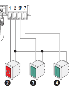 By default, button 2 (STOP) is disabled and button 4 is configured as "step-by-step" mode (open-close).
We need to change the controller configuration as follows:
By default, button 2 (STOP) is disabled and button 4 is configured as "step-by-step" mode (open-close).
We need to change the controller configuration as follows:
- “F1=ON” to activate button 2 as “stop”
- “F7=3” to configure button 4 as “close”
- “F8=2” to configure button 3 as “open”
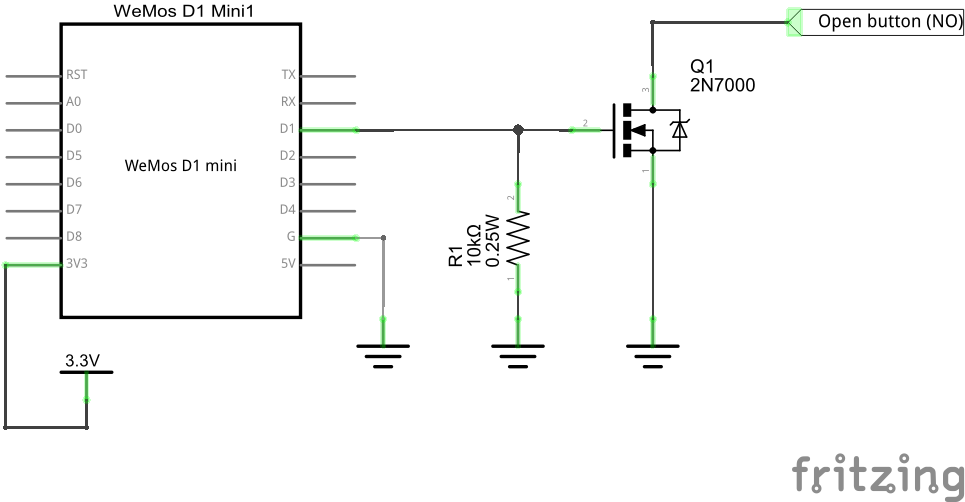
A few measurements indicate that the controller has pull-ups of 4.7KOhm to 5V on each contact, so connecting a N-channel MOSFET (2N7000) to GND, driven by a 3.3V pin of the ESP8266, will fit the bill.
Important note: I checked that all signals we will use below are referenced to the same ground. So connecting the CHAI ground to terminal 2 of this connector will make sure the two boards share a common ground.
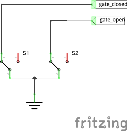
Buttons 2 and 3 are Normally Open, so a 10kOhm pull-down on the gate of the MOSFET will make sure that they are not "pressed" active when left floating (even in case of reboot or power loss). The schematic is as follows (note that the final selection of ESP pins will be made later, this is just to show the external circuit logic):
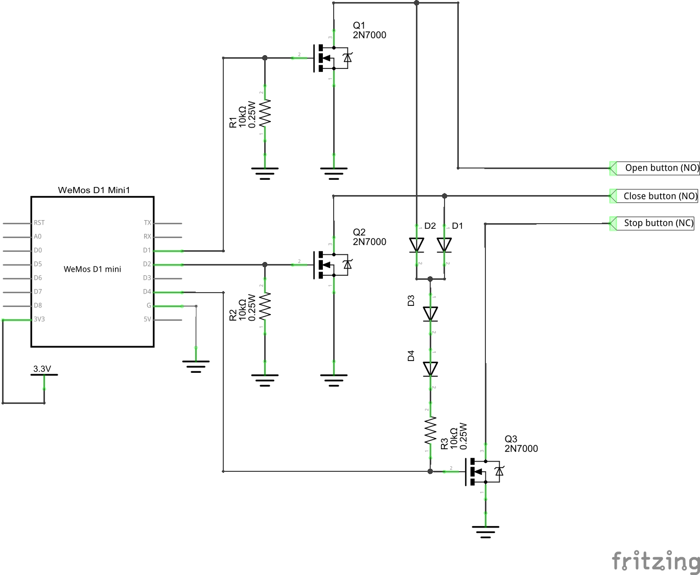
 The STOP button, however, is Normally Closed (it can be used as an Emergency Stop button). In other words we have to make sure that the connection remains closed (MOSFET gate high) by default.
To achieve that pull-up even in case of power loss, we'll derive power from the other buttons, 2 and 3 (through 2 signal diodes (e.g. 1N4148) and a 10kOhm resistor to avoid interfering with those signals).
We'll also put two more diodes in series to drop the voltage and avoid exposing the ESP8266 input pin to a voltage above 3.3V. Something like:
Sensing limit switches
The CAME motor and controller also contains 2 limit switches connected to the controller's F/FA/FC terminals:
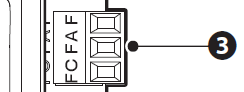
The limit switch themselves consist of a single spring that gets pushed left or right when the gate is fully open or closed, and flips one switch or the other:
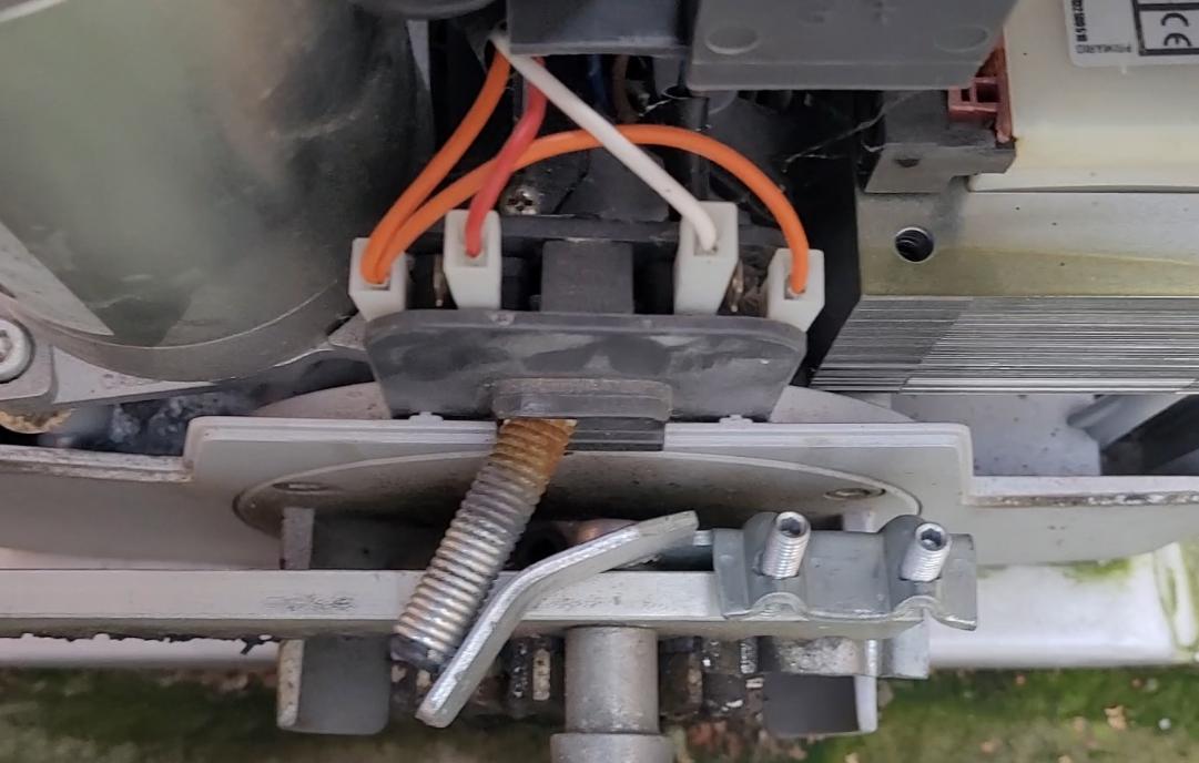
The original schematic is as follows:
- F (orange wire) is GND
- FC (red wire, on the left) is held to GND unless the gate is fully closed.
- FA (white wire, on the right) is held to GND unless the gate is fully open.
The complementary outputs of the switches are located between the orange and red, and orange and white terminals, and are not used by the CAME controller.
When not held to GND, FA and FC are pulled up to 5V by the controller.
Instead of connecting in parallel to those red/white wires and having to deal with level conversion from 5V to 3.3V, I simply used the complementary outputs of the switches, connected to an ESP pin (via a 560Ohm protection resistor - cabling errors happen, ask me how I know ;-)).
The ESP pins are configured with an internal pull-up to 3.3V, so those wires are at 3.3V unless the gate is fully closed or fully open.
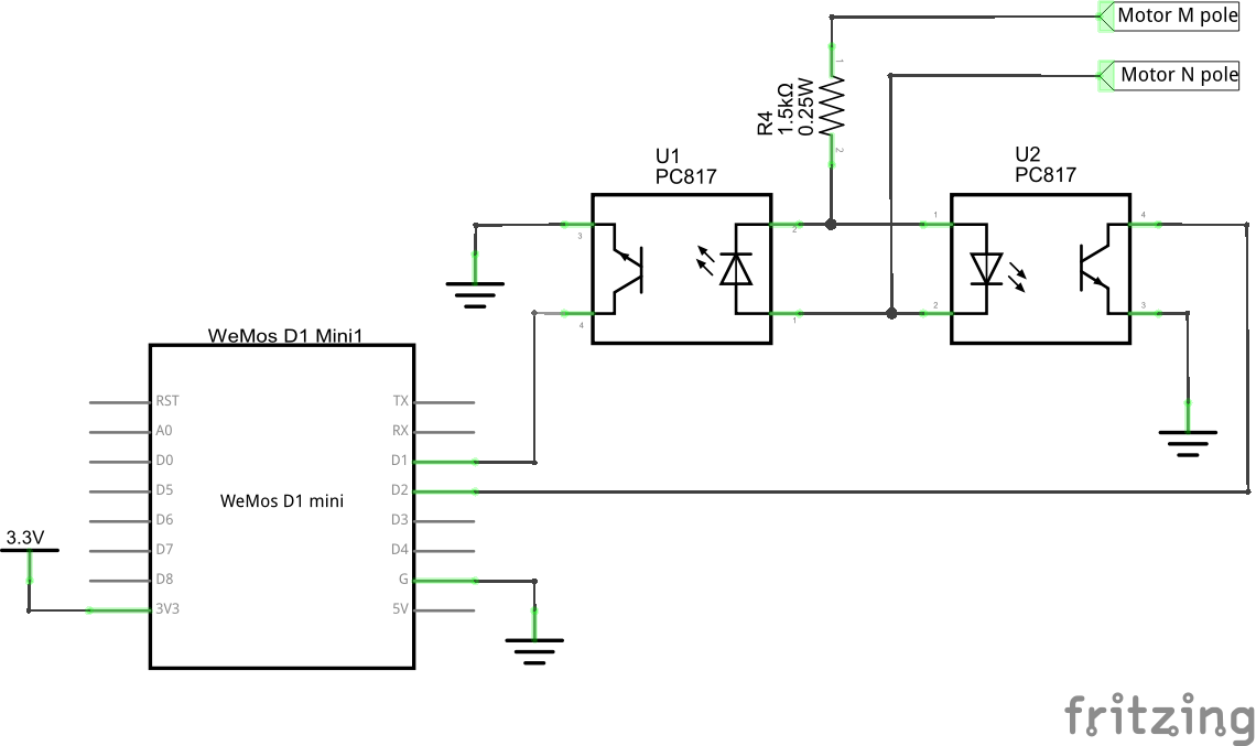
Sensing motor movement
The motor is powered by the controller via terminals M/N (1 on the schematic below), and an encoder gives positional feedback to the controller through the terminals labeled +/E/- (2):
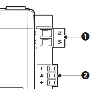
The measured DC voltage across terminals M/N is:
- 30V when opening at full speed
- 15V when opening at half-speed (approaching fully open)
- 0V when the gate is not moving
- -15V when closing at half-speed (approaching fully closed)
- -30V when closing at full speed
At first, I wanted to retrieve information from the encoder terminals. However, I could not make sense of the observed signals, which look like this:
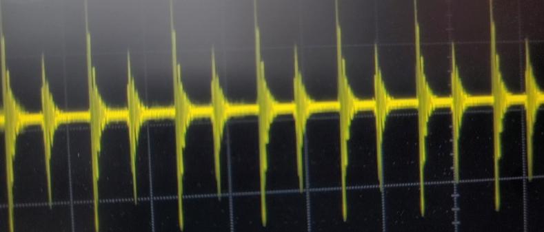 (strangely enough, the small peaks between the big ones only appear at half speed).
I might have measured wrong. If anybody has sucessfully decoded that signal, don't hesitate to reach back to me... I might make a version 2 .
Anyway, in the meantime, we'll use the time of travel in one direction or the other to get an estimate of the gate position (remember that the end positions will be known for sure thanks to the limit switches).
To achieve this, we will just need to know when the gate is moving, and in which direction. The easiest way is to check the motor terminals voltage, but to handle negative voltages, and to protect the ESP from "high" voltage and spikes that could happen at the motor terminals, we'll run them through optocouplers (one PC817 in each direction), as follows:
Reading IR sensor
Although not used in any way by ESPHome's "covers" (*), as we still have a free GPIO, I thought it might be interesting to know if the IR photocell is interrupted. For example, if the gate cannot be closed remotely, that information will tell whether there is an obstacle (car ?) preventing the closing, or if the cause is elsewhere.
According to the CAME manual, here is one way to connect an IR photocell:
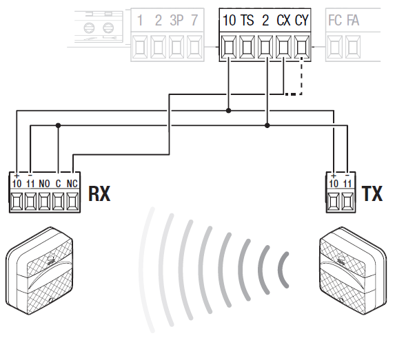
Terminal 2 is GND and terminal 10 is VCC (around 17V). The controller’s CX pin has a pull-up to 5V and is expected to be held to GND by the sensor unless the IR barrier is interrupted.
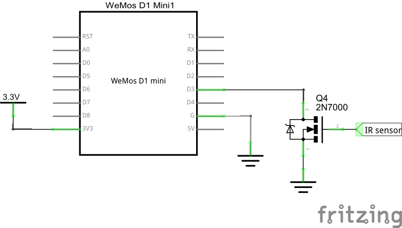
To adapt the level and protect the ESP, I've used a N-channel MOSFET (also 2N7000) as a buffered input as follows:
ESP8266 Pin selection
The ESP8266 (and the Wemos D1) have assigned specific roles to certain pins. Although most can be reconfigured for other uses, the state of the pins at boot time is critical. Some require certain levels for a normal boot to happen, and some are pulled up or down by default. See this excellent RandomNerdTutorlal page for all details.
With the requirement in mind to not interfere with the gate upon boot, I settled on the following pin assignment:
- D1 and D2: movement (motor rotation) sensing
- D3: IR barrier sensing
- D4: STOP button
- D5 and D6: limit switches sensing
- D7 and D8 : OPEN/CLOSE buttons
Final circuit:
Here is the schematic (including a model of the controller to the right of the terminals):
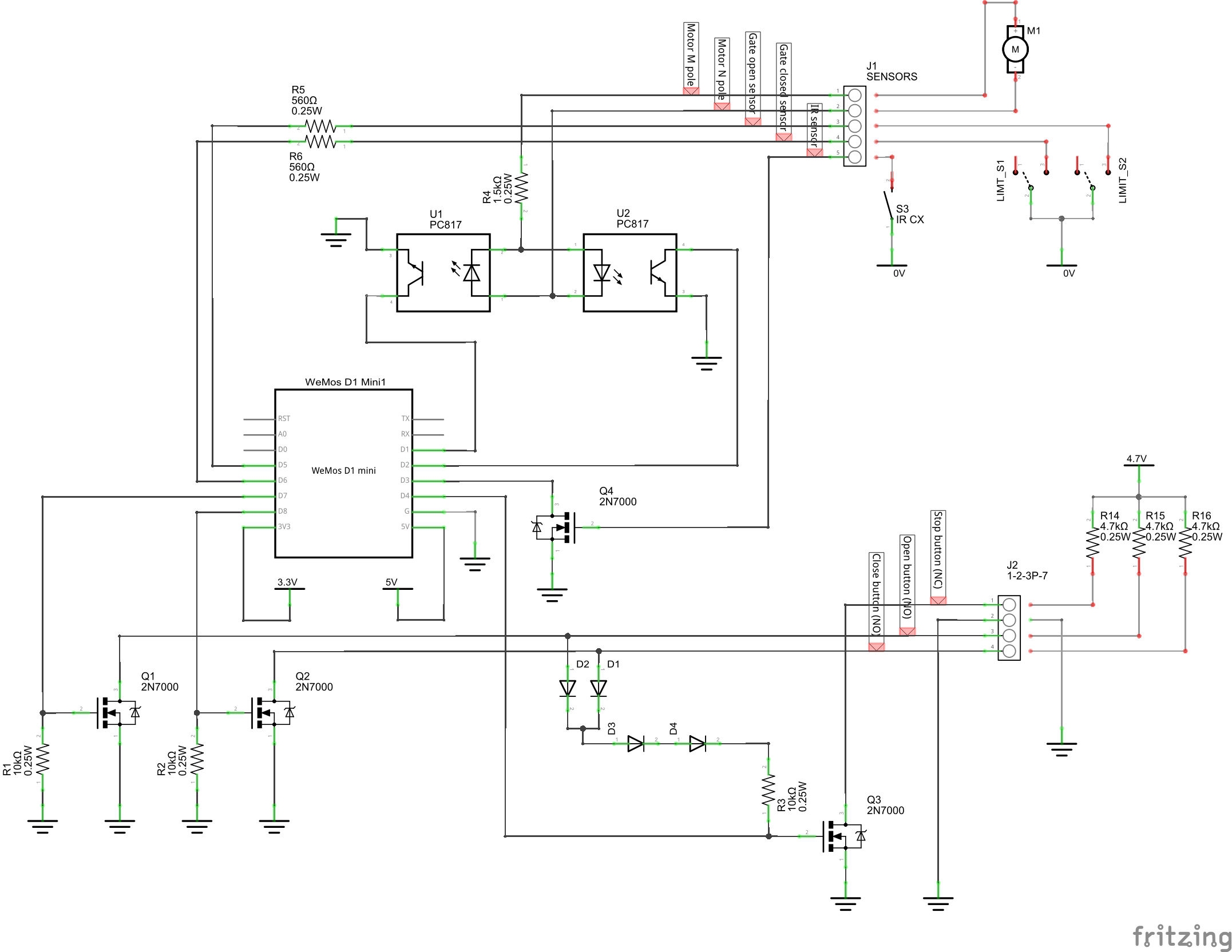
And here is my working prototype (actually, as it is working fine, let's call it the production version :-)):
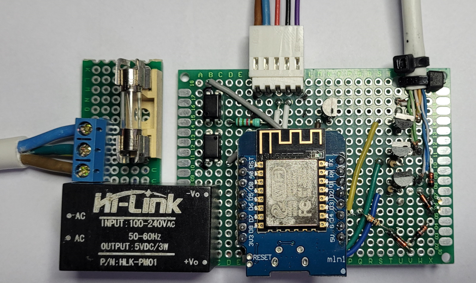
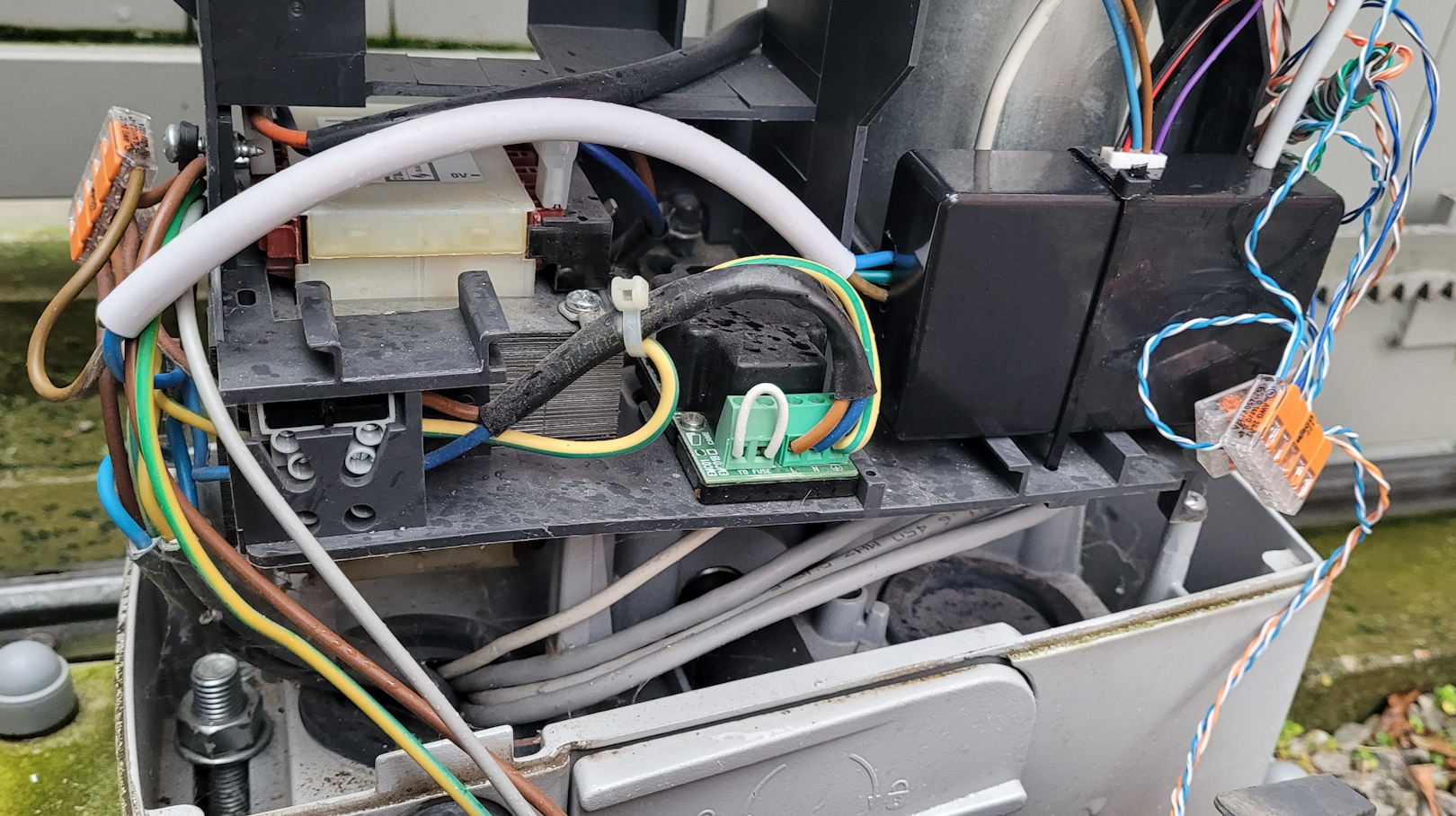
And protected in the black box at the bottom right :
Software design
Environment
As indicated above, I'm using Home Assistant (Important: install it as supervisor to be able to install AddOns. I recommend using Home Assistant OS on a Raspberry Pi), and the ESPHome Add-On for Home Assistant.
ESPHome component
Parking gates are part of ESPHome's "covers" (*), and several variants are supported. As we have limit switches that provide feedback to the ESP, the variant used here is called "feedback cover", which is part of the "time-based cover" family. In other words it can translate the "time of travel" to a position (in percentage) and conversely.
Like most configurations in Home Assistant, the ESPHome device is configured using YAML. Apart from the boilerplate sections (network connectivity, over-the-air update, possibility to force a reboot and get uptime and Wi-Fi quality metrics), the code defines mainly 3 outputs for the open/stop/close buttons and 5 binary sensors for the limit switches, motor sensing and IR barrier. Then, based on those, the "ParkingGate" cover is created and configured with the full opening/closing time (measured at 20s in my case) and a duration to emulate the button clicks (I used 300ms).
For debugging or lower level access, I also defined 3 "button" controls (to be able to bypass the cover and direcly simulate keypresses), but they are not needed for a functional gate. Similarly, I added a "name" field to the 5 binary sensors so that they show up in HA, but a name is not needed for the cover to work, and only the cover itself has to be given a name to be displayed in HA.
Optional feature - "Postman" script
Finally, the "postman" feature allows one to flip a switch in HA to trigger the following sequence to let a delivery guy leave a parcel inside: open gate partially / wait for 1 minute / close gate.
That feature is mainly a script, associated with a "switch" UI component that turns on and starts the script when you click on it, and turns off when the script is finished (with a bit of fiddling so that the script stops if you flip the switch back to off when it's running). Obviously, the postman script is completely optional.
Final configuration
Here is the complete YAML file I'm using:
esphome:
  name: "esp-parking"
  friendly_name: ESP Parking

esp8266:
  board: d1_mini

# Enable logging
logger:

# Enable Home Assistant API
api:
  encryption:
    key: "************"

ota:
  password: "************"

wifi:
  ssid: !secret wifi_ssid
  password: !secret wifi_password

  # Enable fallback hotspot (captive portal) in case wifi connection fails
  ap:
    ssid: "Esp-Parking Fallback Hotspot"
    password: "************"
  manual_ip:
    static_ip: ************
    gateway: ************
    subnet: ************

captive_portal:

output:
  - platform: gpio
    pin: D7
    id: gate_control_close
  - platform: gpio
    pin: D8
    id: gate_control_open
  - platform: gpio
    pin: D4
    id: gate_control_stop
    inverted: true

binary_sensor:
  - platform: gpio
    id: is_gate_opening
    name: is_gate_opening
    pin:
      number: D1
      mode:
        input: true
        pullup: true
      inverted: true
  - platform: gpio
    id: is_gate_closing
    name: is_gate_closing
    pin:
      number: D2
      mode:
        input: true
        pullup: true
      inverted: true
  - platform: gpio
    name: "Gate obstacle detected"
    pin:
      number: D3
      mode:
        input: true
        pullup: true
      inverted: true
  - platform: gpio
    id: is_gate_open
    name: is_gate_open
    pin:
      number: D5
      mode:
        input: true
        pullup: true
      inverted: true
  - platform: gpio
    id: is_gate_closed
    name: is_gate_closed
    pin:
      number: D6
      mode:
        input: true
        pullup: true
      inverted: true

cover:
  - platform: feedback
    device_class: gate
    name: "ParkingGate"
    id: parking_gate
    has_built_in_endstop: True
    open_action:
      - output.turn_on: gate_control_open
      - delay: 300ms
      - output.turn_off: gate_control_open
    open_duration: 20s
    open_endstop: is_gate_open
    open_sensor: is_gate_opening
    close_action:
      - output.turn_on: gate_control_close
      - delay: 300ms
      - output.turn_off: gate_control_close
    close_duration: 20s
    close_endstop: is_gate_closed
    close_sensor: is_gate_closing
    stop_action:
      - output.turn_on: gate_control_stop
      - delay: 300ms
      - output.turn_off: gate_control_stop

script:
  - id: postman_access
    then:
      - cover.control:
          id: parking_gate
          position: 25%
      - delay: 65s # must be = opening time + duration of the "open" phase
      - cover.close: parking_gate
      - delay: 8s # must be = closing time + a few secs (motor slows down when nearing full close)
      - switch.turn_off: postman

switch:
  - platform: template
    name: "Postman"
    id: postman
    optimistic: True #otherwise it turns off automatically after a delay as it has no confirmation of a state
    turn_on_action:
      - script.execute: postman_access
    turn_off_action:
      - script.stop: postman_access
      - cover.stop: parking_gate

button:
  - platform: restart # reboot button
    name: "Gate module reboot"
  - platform: output
    name: "Gate control open"
    output: gate_control_open
    duration: 300ms

  - platform: output
    name: "Gate control close"
    output: gate_control_close
    duration: 300ms

  - platform: output
    name: "Gate control stop"
    output: gate_control_stop
    duration: 300ms

sensor:
  # wifi signal level in dBm
  - platform: wifi_signal
    name: "Gate WiFi signal"
    update_interval: 60s
  # ESP uptime (to track reboots, if any)
  - platform: uptime
    name: Uptime Sensor
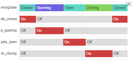
In the UI, using the history explorer Add-On, one can check the cover state changes based on the individual binary sensors:
(*) The ESPHome term "covers" covers (no pun intended :-)) gates, blinds, curtains, garage doors, and basically all home elements that do open or close